Viser opslag med etiketten modular. Vis alle opslag

lørdag den 23. juli 2022

I'm featured in the new issue of Black Panels Only Eurorack Zine! I highly recommend you go get yourself a physical copy. You can read a bit about my synth and how I used the modules for recording my latest album.

fredag den 28. januar 2022

I've released a new album 'Skygge Side B' composed entirely on modular system:


lørdag den 24. juli 2021

Hi everyone, here's a video auto-biography about my artistic journey I'd made during the winter of 2020. It's showing how I started, the road I travelled and where I ended up. Lots of footage of my works, concerts, behind the scenes etc. Thanks for watching!


onsdag den 17. marts 2021

Full albums now on my channel

Hi guys! I decided to upload my two albums on my channel so here goes:


Some background:

'REMNANTS' (2015)
is my debut album I released as my Bachelor's Project under the Academy of Music.
I designed a simple circuit for an audio player and composed an album out of recordings
from my various audio material from my DIY projects.

RECLUSE [2020]
is my second album I composed just before the pandemic in a somewhat depressed but lucid state,
after dropping out of my Master's study due to health problems. I regressed into the past and started
composing music for my newly finished modular system and old tracker software.


onsdag den 11. november 2020

Eurorack Modules: DIY CRT scope

Hi guys, I know it's been a while.
I've fallen behind with updating my blog although I've been active on my facebook and my YouTube pages. Sometime back in 2018 I decided to switch to eurorack as my DIY stuff required a lot of maintenance. I uploaded this video of my current studio recorded with an old crappy camcorder where you get the general idea of the setup:


I've bought several weird modules which sort of fits into my previous aesthetic with vero test-boards, bendable CMOS-chips, tube-amplifiers, CV-controllable tape-player, nixie tube counter and a custom built CRT-scope module I designed in collaboration with a tinkerer from Belarus under the name Ghetto Hacker. 

I stumbled upon this Ghetto Hacker guy where I saw he'd built a module for eurorack with a small CRT from a camcorder, used as an oscilloscope. I paid him for his time and skills to make me one and the result is really amazing, sturdy 3d-printed arm to hold everything in place and a nice black front plate.
 
Here's some video:

Ghetto Hacker's finished work:
 
 
Testing module in my own case:

 
 And here's some pix from the build:

Blueprint for mounting
Layout for front plate
Front Plate done!
CRT installed
Under construction
Finished module installed

If you're interested to see what I'm up to, go follow me on YouTube (Dani Dogenigt) or find Dogenigt on facebook. I think I am going to give a guided tour of my eurorack system so you can see some of the modules in action. Please take care and see you soon!

lørdag den 17. marts 2018

Yearly recap

All right so it's been over a year since I last made a new post here. A lot has happened in this period.
First of all my .com domain expired and before I got the chance to renew I discovered to my surprise that it'd been bought by someone else, I suspect godaddy does this to get people to negotiate a buy-back fee which is a dirty move so right now you can find this blog on dogenigt.blogspot.com

I've been moving a lot so all my gear and the entire workshop is currently stored in my rural home where I am renovating so I haven't been able to build and produce anything.
I also chose to cancel my studies for my master's degree at the academy of music due to stress and other health issues so my mind hasn't really been focused that much around electronics and music.
I've been more or less homeless over the (harsh scandinavian) winter and staying at friends but I am moving into an old farmhouse with my brother on the 1st of may so my plan is to gather some of my gear and get a small studio going again.

To make a recap of where I left off a year ago,
my DIY modular project was going into all sorts of directions as I was really inspired to do all kinds of raw and untraditional modules.


I got to mounting the magic eye tubes for the 4 channel mixer and the VU-meter nixie tubes for the stereo main out module with EQ for both channels as you can see in the bottom case.
In the top case I mounted volt- and amp-meter for the PSU and a breadboard module with banana jacks for interfacing. This could be a neat little module for testing new circuits and have them ready for experimenting on the go.
The green screen to the far right is actually an old gameboy with backlight with LSDJ cartridge and a vintage magnifier screen from a dias-photo viewer. The red wires going from the gameboy are going to a NES-joypad which I succesfully got working so I'll be able to control the gameboy from afar as the gameboy is enclosed in the case.
On top of the case is my microcassette tape delay and two cassette tape players from a stereo tape deck which I am planning on building into a third case for a tape delay.
On the far right is an old tape player from a car stereo which I want to make into a monophonic tape voice unit with CV-control for the motor to control the pitch.

More to come!

torsdag den 6. august 2015

DIY Modular #1: Wooden case and CRT-monitors.

Hola amigos y amigas! :-)

Besides enjoying a long summer holiday, before starting on my master's degree in electronic music,
I've been rethinking my entire setup and decided to abandon the idea of having lots of separate boxes which I have to arrange and connect for every concert and instead jump on the modular wagon but with my own standards and designs.
(no "eurocrack" ;-P )

I am going to design and build every module from scratch and include some different and unique modules and parts and try different methods of circuit designing. The frontplates are going to be transparent so all the insides are visible, which adds an extra dimension the the machine - it will be an work of art, from circuit to interface.

I wanted something organic and easy to work with so I went with wooden frames for the cases and for the front- and backplates I chose transparent acrylic glass as it's neat to be able to see the insides of the machine. I will put a lot of emphasis on the aesthetics of the circuits, parts and components because of this. For attaching the acrylic frontplates I am going to use an alu-rail with rectangular 'slide nuts' as the width of the modules will vary.
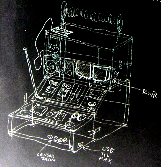
In the future I want to be able to expand with further identical cases on top so I added a mechanism for attaching the frames to each other. The drawing above shows my vision of what the machine will ultimately end up looking like.

Some snaps of the cases / frames:
Wooden frames with plexi back plate

Single frame / case

Both frames attached

I found it crucial to start with the design of the power supply part. I had an old PSU from a laptop lying around - 19V DC with app. 5A of juice to play around with. Some of the parts will be quite power-hungry so in the future I might have to step it up to 10A. I found a cute old capacitor from Denmark and decided to use it as stabilizing cap. My plan is to have most of the modules run on  ±12V but I might add a 5V line as well but so far I've been using LM317 variable voltage regulators for each device.
Power connector and switch w/ LED
Rear view - large capacitor added
Personal notes on PSU

The first actual modules will be a 'terminal' with a green-monochrome CRT TV. It will receive a video signal from an Atmega328 generating simple text strings with data such as the temperature inside the box, total run time, date and time and a lot of other stuff.
Next to it another CRT TV of the same size will display the master stereo output as a simple oscilloscope. Beneath the TV I will install two analog VU meters with a nice warm backlight as well.

Shelf for the TV's and front plate test
Side view of the shelf
Rear view of the CRTs
Both TVs turned on!
VU meters on as well. :-)
Startup-text generated by the arduino
An analog current panel meter will be beneath the terminal showing the power usage for alle the modules. Each TV draws around 1000 mA but so far 5A in total should be enough. I've used 7812 regulators for each TV to supply 12V but the regulators turn very very hot and will shut off without proper cooling so I had to mount rather large heatsinks.
The plan is to mount front plates in front of the TV's and have all the knobs and in/outputs controlling the TV and the terminal.

For labels I want every front plate etched with a CNC router (or just by hand?) and then edge-light it with an LED-strip installed beneath the acrylic. A test looks like this (scrap acrylic with scratches):
LED-strip test
Edge-lighting test
Edge-lighting test

onsdag den 28. januar 2015

Aristoteles Logic Synth Update #5: Sequencer

I couldn't hold myself back after finishing the AND-gate module for dear Aristoteles so I dug up the schematic I drew for the 10-step sequencer module and jumped right in. In the video below I'll demonstrate how it works and the possibilities are vast! Combined with the AND-gates it's very convenient for creating melodies and patterns.


The sequencer is based on the '4017 CMOS Decade Counter' which counts from 0 to 9; adding 1 every time a clock pulse is received on the CLK input. It has 10 outputs going high/low one at a time depending on the current count. Only one output at a time can be high; the one corresponding to the count.
There's a reset pin which decides when the counter will reset to 0 so it's possible to have it count to any number below 9. I've implemented a rotary switch for setting the count from 9 to 0. If the reset pin is set to ground, the count limit will be set to 9 (default).

If an audio range signal is sent to the clock pin and one listens to one of the outputs, you get harmonic intervals when reducing the count limit. This makes sense as it only takes half the time to count to 5 instead of 10.
The frequency ratio to the frequency we get when counting to 10 (which can be seen as our fundamental) can be calculated by dividing 10 with the desired count. So the relation between i.e. 10 and 5 (10/5) is 2. We multiply our fundamental with this number to calculate the interval, which in this case would be an octave.
The chart below shows the intervals we get when we're adding the value of the fundamental - which is what happens every time we add a step for the counter. Interesting stuff!


Multiple of
fundamental
Ratio
within octave
Common name Hz and chroma
(Example)
1x 1/1 Fundamental 110 (A2)
2x 2/1 Octave 220 (A3)
3x 3/2 Perfect Fifth 330 (E4)
4x 4/2 Octave 440 (A4)
5x 5/4 Major Third 550 (C5)
6x 6/4 Perfect Fifth 660 (E5)
7x 7/4 Harmonic Seventh 770 (G5)
8x 8/4 Octave 880 (A5)
9x 9/8 Major Second 990 (B5)
10x 10/8 Major Third 1100 (C6)


As is the custom, I've attached the scheme for the circuit for this module. It's not that intricate, just LED's and output jacks on each output. I see that I forgot to add the transistor LED-drivers, but it's just as usual - look in the schematics for the other Aristoteles modules to see how they should be wired.
I've used a 12 position rotary switch for the reset switch, I couldn't find any 10-pos so 2 of the positions are grounded which just sets the count limit to 9 (all 10 steps). It can be tricky to find out which pins correspond to the switch positions but easy enough when using a multimeter for testing continuity between the output and the desired pin.

I will post all my stripboard layouts in a single package when I am finished with the last module :-)

 UPDATE 7/2-15:

My brother and I (as the duo SNU) had a really nice jam with the Aristoteles modules so far.  Here's a video of  our session when the sequencer was still on breadboard. I had my Clock Box (which also runs on 40106 and 4040 oscillators) control the power for the 4017 so a lot of modulations back and forth.


fredag den 16. januar 2015

Aristoteles Logic Synth Update #4: Logic Gates

I thought it was time for building the next module for dear Aristoteles, my 'lo-fi logic synth project' so I did the logic gate module which consists of 8 AND gates with 2 inputs and an LED for the output. The truth table on the right describes how the gate will behave: the output only goes high (1) when both inputs are high. The result is a very simple form of amplitude modulation, or it can be used to control the path of signals from the other modules with counters or LFO's, you name it. 

The video below speaks for itself.


In the video I demonstrate the effect of the 3 different frequency ranges on the oscillators: LFO range signals are good for 'letting through' audio range signals at a certain rate for "beep beep beep beep" sounds. 2 audio range signals will generate complex pulsating modulations and beatings when adjusting the pulse width.
Setting the range to the high pitched setting on both oscillators will generate classic vintage radio-like modulation squeeks. I also tried using the 'octave divider module' for one of the inputs which has its own unique sound.

I chose to have all the logic gates as AND gates. For a long time I was in doubt about wether to have a pair of XOR or NAND gates just for the hell of it but I could not find a good reason as they don't do much sound-wise where as the AND gate is so clear in its function and I want to be able to make complex signal paths with counters, dividers, random clocks and all eight oscs - all controlling each other through the gates. 
I am already starting on the 10-step counter 'cause I cannot wait to have each step 'open' a unique oscillator with different frequencies!

The circuit is very simple, I basically just wired the in- and outputs straight to the 4081 but attached 100K resistors on each pin to prevent static electricity from the end of the wires going into the chip when patching.
LED's are controlled by transistors as always to prevent voltage dropping on the outputs.


UPDATE:
I had my brother a.k.a. SNU over and he fell in love with the new module which resulted in hours of wiggling.
Here's a a little peak of the tweak :-)

onsdag den 7. januar 2015

Terrestrial Signals III Live concert @ DIEM Elektro 'Pulse'

A late happy solstice to all of ye - I have been ind bed for most of the holidays, guess my body and mind was in need for some rest, it's hard work wanting to do you own thing and the following concert you are about to witness required a lot of planning and soldering.
I found out I was booked to play at the next of DIEM's obligatory student concerts 'DIEM Elektro' - this specific concert was called 'Pulse' so I prepared some pulsating light-controlled rhytms with a hacked monotron, using only the nice korg filter with a photoresistor, clock-synced to the notorious MicroWaveSampler by my Clock Box. I included my electromagnetic plasma ball synth described in the post below. I was pretty content with the outcome although some of my gear failed a bit, including my little TV-to-sound device. To much noise on the line to gain it. Anyways, please check out the video - it was shot by my brother Alec Sander and with his GoPro Hero camera attached to my head so you get the P.O.V. close up shots from my perspective. Enjoy!


I have a line of projects planned for this year, as I am writing my bachelor project which I think will focus on alternative media for releasing album material, more to come on that. After the last concert I finally chose to sucumb to the idea of a modular system instead of all these seperate modules which has to be wired together on set, it's too much hazzle every time I need to set up for a concert so now I will jump into building a complete modular system with the same principles used so far: analog means of sampling, tape delays and quirky little circuits. Stay tuned!

Lot of love, Dogenigt

fredag den 5. september 2014

Aristoteles Logic Synth Update #3: Divider (simple)

The Aristoteles 'Lunetta' synth project is slowly but steadily going in the right direction. Here's the first of the two 4040 divider modules, demonstrated in the vid below.


Here's a scheme for the willing - simple and self-explanatory!

To explain this simple circuit in a simple way, it's taking any clock output from the other modules and counting 2^n times before setting the output HIGH - 2, 4, 8, 16 and so on - up to 2^12 times, that is 4096 clocks before setting the output high.

That's quite a division, so a high frequency is needed if one wants oscillations in the audio range. Otherwise it's great for turning audio range signals into LFO clocks. All in all, it's a very musical chip as it creates sub-octaves, which are relations of a factor of 2 to the input frequency.


I was flipping through Roads' Computer Music Tutorial one evening and began to read up upon the very first digital systems with flip-flop logic gates and discovered that the method of dividing down a master clock to acheive other tones is ancient! So-called 'divide-down tone synthesis' was discovered in 1930 so this method is almost a century old!

lørdag den 12. juli 2014

Aristoteles Logic Synth Update #2: Oscillators


The next module on the path of Aristoteles, the 'lunetta-style' synth, is finished! It's the central part of the synthesis: Oscillators. 8 of them. So essentially one could patch all 8 oscs into the 8-channel mixer and have 8 voice polyphony. They will also serve as the unique pseudo-CV clocks for the other modules, which is the main concept of CMOS-based synthesizers. The brain in all this is the classic 40106 chip, which is actually a logic NOT-gate flipping on and off. Below is a quick demo.


The oscillators have the following functions, as seen on the image to the right:
The first switch lets you choose if the osc should be constantly on or momentary, determined by the red button. This allows one to use the synth as a simple keyboard with a little willpower.

Next switch allows you to add extra capacitance to the oscillator, thereby setting the frequency range. The middle position of the switch is actually an off-position so the oscillator runs on the "offset cap" which is too small at the moment, so the frequency is very high. I wanted to have this range-switch so I could go with a potentiometer value around 100K for the frequency knob. This makes it easier to tune it without too big steps, as one gets if running on 1M or something in that range.

I chose to have the whole synth only producing square waves, to have it ultra lo-fi and simple. But I  thought it could be nice to at least have PWM for each osc though, so this is what we have below the freq pot.
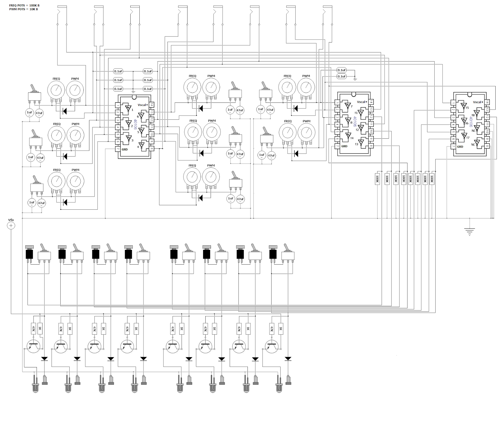
 It's a simple diode technique for adjusting pulse width of the wave, but I discovered that it was actually an inverse PWM, for what I wanted. It was setting the lenght of the off-time, not the on-time, so the LED's would be constantly on, only turning off for a short time, so I used another 40106 to inverse the HIGH/LOW order. This is the reason for 3 of the chips in the design - 2 IC's for getting 8 oscs and another one plus the leftover gates from IC 2 to have the pulses inversed.

The LED's are switched on and off with the help of transistors, to minimize voltage drop on the outputs. All the outputs are grounded with 100K resistors as well to prevent frying the chip if you touch the banana jacks.

Here's my quick and dirty schematic drawn in MS paint :)
Feel free to use it for inspiration in your own designs.

fredag den 23. maj 2014

Aristoteles Logic Synth Update #1: MIXER

Oh what a spring it's been! I was bedridden for about a month which really zapped all my creativity and I've slowly recovered now to bring back my mind on what is the icing on my cake of life: electronic gadgeting.

So just around New Years Eve I posted a picture of my newly assembled modular synth casing - no intestines yet though! But just before my bed claimed me for a minor lifetime, I was able to finish up the first and central part of the system: the 8-channel mixer with simple BP/LP filters + power supply.

Here's a demonstration of what I am talking about:


So the idea is that you have 8 channels in the mixer which are summed together after they've passed the filter circuit and the respective volume knob. When using stackable banana-jacks one might ask why bother with a multi-channel mixer; why not just stack 'em on top of each other and using passive resistor/diode mixing?
The problem for me was that mixing with just resistors would cause each output from every oscillator to drop in voltage and maybe cause instability with edge-detection in the chips they would enter - and diodes make distinctive modulation when used for summing. Which is why every output enters a diode, so it's still possible to mix signals together in a single mixer channel if one is running low on free channels. Other than that, diodes make sure that no cross-talk occurs if stacked for multiple operations.


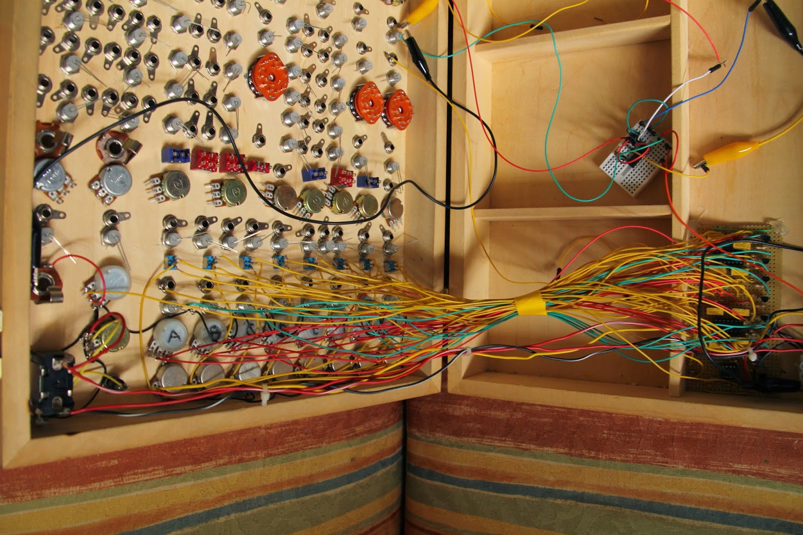
Some pics:


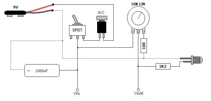
The power supply was super simple, just a power switch and momentary N/C button to switch on  and off and discharge the 470uF cap to get the power starve effect. Starving only affects the CMOS-chips used for sound generation, the mixer circuit isn't affacted by the variable supply voltage.
I will discuss the other modules in future entries and here's some schemes for the willing.


tirsdag den 21. januar 2014

Greeting Card Sampler Boxed

I finally got to finish up my project seen in this previous post: Voice Message Greeting Cards turned into Lo-Fi Sampler. It's the 'voice message recordable greeting card' I hacked into a small looper with playback speed bend, now in a neat little encasing I found in a thrift shop. I think it's a intercom from the 70's, quite nice.


The video shows the features which are: potentiometer for varying the playback speed, switch for selecting loop mode, red button on the side is for restarting the device, which re-triggers the message, switch for selecting between the inputs - electret mic or input jack, jack for sending output to an amplifier and in the bottom are two banana jacks which allows you to control the device with a vactrol or light sensor, or any other resistive sensor :)


I had a very nice day at the FabLab's Maker's Day in Copenhagen, where I held a small symposium and a koncert with my current setup. One of the guys from CEO Bendorama who also played, got a recording of my concert - which includes the Greeting Card Sampler. (Thanks John!)