tirsdag den 31. december 2013

See you in 2014!

Dear readers, thank you so much for showing interest in my projects - I can't wait to show off all the coming projects I've got up my sleeve for you! Here's a snapshot of my largest project so far: ARISTOTELES! It's going to be a "logic" modular synth. I couldn't wait any longer with revealing it, I've just attached all the knobs and jacks to the box - stay tuned, happy new year and see you in 2014! best wishes, Dögenigt.


mandag den 16. december 2013

Live concert in cold war dome bunker

This autumn, several empty or unused spaces in Aarhus were turned into cultural platforms, amongst them were a minor cold war dome bunker where artists from DIEM were invited to perform a handful of intimate concerts for a small crowd. The event collided perfectly with the finalizing of my MicroWaveSampler - so my setup consisted of that, my Microcassette Tape Delay and my Spring Reverb Module. I borrowed my brother's GoPro Cam to record the concert from my POV.


Concert program folder showing inside of the dome

I'd recorded a sample bank for the MWS from instruments and other acoustic sources in my studio (the same samples used in this track) which brought a strange shamanistic and mystical vibe into the bunker. The lower frequencies, mostly from the shaman's drum-samples, resonated quite a lot in the room which you can hear in the video.
I didn't bother to tame the spectrum, I knew the room would be quite unique with some heavy room modes so I chose to embrace this and get a natural communion going with the dome. Improvising was nice because it allowed me to adjust to the surroundings.


Snapshot of my setup


I brought my crappy behringer mixer to be able to control the signal path and mix between dry/wet. But basically the main sources were the (microwave)sampler and a simple contact-mic bass-guitar which were sent to the mixer and then sent via a 'send' channel to the Tape Delay, back into the mixer and via the other send channel to the spring reverb. The reverb has dry/wet control built in so I could control the amount of reverb - which was convenient at times as the spring started oscillating very easily. I enjoyed the concert a lot, and it was quite exciting to perform with this setup!

søndag den 6. oktober 2013

The MicroWaveSampler!

It is with great joy I am able to present to you: our dearest little newborn, The MicroWaveSampler.
An Arduino/Adafruit WaveShield-based 'Lo-Fi' Sampler with 16-step sequencer, preset function and external clock.
A project between my best g33k-buddy Carl @ DimsOs and I, which has been underway for a year.
We chose to call it MicroWaveSampler because it's a Microprocessor-driven Wave-sound Sampler.

Here it is in action, bellow we'll dive into the intestines.


I bought the Wave Shield some years ago and always wanted to make some simple sampler from it - I was thinking something very mechanical with rotary switches but as Carl made me aware of, the ATMega328 IC holds great potential for internally taking care of all sequencing and triggering of the samples on the card.
This awareness was the first step on the path to creating a fully functional sampler with the arduino. It turned out that we had to be very creative not only with the programming but also physically and circuit-wise, making the most of the fairly limited microprocessor IC. On the layout below, you can see the physical concept of the constellation:


So the brain of the game is of course our microprocessor, the Atmega328. It reads the WAV-files from the SD-card. We have a GUI in our little 16x2 LCD which shows our 16 steps/samples on the bottom line, each soundfile on the card is assigned a unique ASCII character, and since it's a chinese LCD we're using we have 185 symbols available (minus the ones we are using for common indicators etc).

For selecting steps and step menus (functions) we've built arrays of pushbuttons going through R2R-ladders, which means that each button sends a unique voltage to one of the AIN's on the atmega. The video shows how this is implemented but you select the step you want to edit and set the sample #, the sample rate and muting

Stripboard layout
For our "rotary encoder", we had to be creative as we were in need of a pin because of the display and the DAC, so we decided to use a DC-motor as our 'select-wheel', so just one AIN reads the voltage coming from the motor - if we spin it right, the reading is positive, spin it left and the reading is negative. That way we can determine which direction the motor is being spinned.

There's a knob for adjusting the internal clock (metronome) speed and one can switch to the external clock to syncronize with other devices. We've implemented a little button in the lower right corner for manual clocking if one doesn't have his Clock Box at hand.

Last but not least, the microprocessor sends the data to the DAC, which converts it to analog signals, amplified and sent to the audio jack.

We thought it was a good idea to go ahead and get the whole thing soldered together before engaging in the programming process. So we designed a stripboard layout and soldered everything together.
Actually we wanted to have the everything on a single stripboard, but as I already had my Wave Shield soldered up, we decided to use that and make pin headers for the shield which is nice because it saves quite a lot of space on the board. To have easier acces to the buttons while programming and testing we mounted everything in a cardboard test-box which made it look pretty sweet and silly :-)

Stripboard done
Wave Shield and LCD mounted
Everything soldered together

Now when the intestines where firmly put together, we could start experimenting with the software. It was without any doubt the most thrilling part of the whole process. To invent a small program for the machine and watch Carl code away for hours and hours. I am quite novice-level when it comes to programming so it was really a gift to have a skilled programmer design the brain for the device from my ideas. I would lay in bed before going to sleep getting new perspectives on how to implement the features needed and write them down on paper to show him so he could get an idea of how I wanted it to be.

The code will be available in the future, it still needs some polishing before it's ready for the public.

One of many code-nights @ DimsOs
Blueprint for program
Screenshot of the extensive code!
After 9 months or so, about as long as it takes to give birth to a little beauty like this, the horizon of completion came closer and it was time to get the thing boxed in it's proper casing. I got a obsolete television-channel box from my mother-in-law with a nice thin metal front-plate. I had MadsT, the the skilled carpenter and other half of DimsOs, help me drilling the holes in the frontplate. It required some delicate measuring to get the spacing between all the step-buttons right.

Casing Layout
Encased MWS!
Final Product
It's been such a learningful process and it really pays off to be persistent and patient: to be able to have a personal music device designed to fit your own basic needs.

In the future we plan to make a version 2.0 - the design will be quite different, not so unorthodox as this one. If everything goes right, we will be able to provide DIY-kits with these. I'll let you know!
As before-mentioned, the code will be up soon, I will update this thread when the time comes.
Feel free to write us, comment and share!


UPDATE October15h, 2013:

I did a recording session for the virgin concerts with the MWS, recording all sorts of concrete sounds in my lab, acoustic instruments and such. Made a multitrack session in Reaper with the beats, the result was pretty nice.

onsdag den 21. august 2013

Spring Reverb Module

After a nice long summer holiday with plenty of time for contemplation and relaxing, I felt it was time to return to the workshop and strike while the soldering-iron was hot so I finally finished my spring reverb module which had caused me some headaches during the spring time (no pun here). During trouble shooting, I've learned a lot about operational amplifiers which will be useful in future builds.

Here's the finalized contraption in action!


It's basically a Spring Reverb Tank (the ones you find in old guitar amps) for which I've made an amplifier-circuit. The 'IN' knob controls the gain for the signal sent into the spring, the 'DRY' knob lets through some of the clean signal to the internal mixer circuit and the 'WET' knob sets the gain for the signal from the spring tank to the mixer. This lets you just plug one jack-cable into the module and adjust how much of the clean signal you want to blend with the reverbed sound - saves a lot of cable mess. The input gain acts as a kind of "decay time" as it somewhat determines how long the spring will vibrate for because of the amplitude sent to the spring.

I also found out that you can get nice feeding oscillations if you turn off the input sound! (happens in the end of the video)


I feel this is kind of a 'must have, must build' module for anyone serious about having a handmade modular setup, so I was very determined to get this done and now I am so relieved about finally having this mo-fo boxed and good to go so I can focus on the larger projects I am about to unveil for you good folks out there!

Here's my scheme for the amplifier-circuit:


I chose to use seperate ICs to avoid bleeding of the signals, which I encountered on the test-board. I see that I didn't bias the mixing stage, but it sounds good without.

mandag den 27. maj 2013

Clock Box v1.0

I wanted to be able to sync my various modules and homemade instruments so I came up with a little device that would produce a main clock with a number of divisions of the main clock for scaling down the tempo but still be in synch with the main clock.


I found the CMOS 4040 IC to be an obvious choice for the mission and the 40106 for producing a clock. The 4040 has 12 outputs which are divisions of the input. That is, it's a counter that counts the input N times before it outputs a HIGH, which is the same thing as having a clock frequency input divided by a factor of N.
The output divisions are /2, /4, /8, /16, /32, /64, /128, /256, /512, /1024, /2048, /4096.
I find the higher divisions to be quite slow so I don't reckon I'll be using them very much.


The device runs on 9V so I'll be installing voltage regulators in my devices I want to sync with the Clock Box, mostly it'll be regulated to 5V for arduino-based modules and floppy drives or 3V for walkman stuff but if I get to choose, I just run everything on 9V as it's easy to test with batteries and switch to a 9V AC/DC adapter for the final product.


I drew this layout for the circuit board, if you are going to build it from this layout note that the numbers indicate the connections between the chips and the 12 position rotary switches.

Gotta love CMOS chips! vast possibilities.

Over and out - yours truly,
Døgenigt

tirsdag den 14. maj 2013

Snaps from the Lab

I thought I wanted to show you a few shots from where it's all going down - I am located in Aarhus, the 2nd largest city in Denmark, just on the brink of the old Moesgaard forest where I enjoy taking walks and getting in tune with my ancestors.
At home I use our bedroom/office for tinkering and chilling, my lovely woman is very tolerant of the mess I tend to make. My brother dropped by on my 27th birthday with his new fisheye-lense and got some great shots of me in my natural habitat.

To the far right, I've placed my Amiga 600 - a must have memento for the g33ks of the 90's
Caught in the act: at the top shelves are my first tape deck ever, a reel-to-reel tape recorder and an old sine-oscillator
Sending audio signal to small television hacked into an oscilloscope (look in post beneath for how-to)
The sine wave oscillator is a donation from a friend's dad who's a physics teacher. Think it's from the 50's/60's.

mandag den 13. maj 2013

Sony Watchman Oscilloscope Hack

This is a demonstration of how you can turn any CRT-television set into a nice visualizer/oscilloscope.
Please take caution when opening up any TV with Cathode Ray Tubes as they can store thousands of volts for a long time after last usage. Use rubber-gloves and ground yourself as a minimum protection. Stay away from the anode (the suction cup hose) as this is the mofo responsible for storing these high voltages.

I take no responsibility for any accidents caused by this guide.
When that's been said - I've fiddled around with quite a few TV-sets during the last couple of years and I have a weakness for very small TV's, so when I came across this Sony Watchman from 1986 (this thing is as old as I am!) which I'd never heard of before, I had to have it as I thought it would be neat as a portable oscilloscope or visualizer for my setup. I am thinking of getting some more of these small CRT's for built-in oscilloscopes in some of my future DIY-synths!

The image to the right shows the Watchman as it were when I bought it, I thought it would be shame to tear it out of its original casing so I decided to keep it intact.


disassembled watchman
gaining access to the PCB
hack done! 


In the beginning I wanted just to have it display the horizontal axis for this traditional oscilloscope-mode but the ray is very narrow this way, only taking up a fourth of the area on the screen so I attached a switch for selecting wether to send the signal to both the horizontal and the vertical axis or just the vertical (signal to vertical axis = horizontal line. Check the wiring circuit further down)
This way it functions well both as a visualizer, showing galaxy or whirlwind-like formations or as a small waveform display.


Here's the final result:


For anyone urging to try it out, I made this circuit which should make things a bit more comprehensible. Wire-colouring of the axis' differs for each TV-set but should be easy to locate as they are attached to the end of the tube. And again: DON'T GET ELECTROCUTED!

torsdag den 28. marts 2013

Microcassette Tape Delay


For quite some time, I've been fascinated about Tape Delays and decided my grand future setup would have to include a DIY Lo-Fi Tape Delay of some sort. I wanted it to be simple, portable and it should colour the sound a great deal, so I chose the Microcassette Tapes for my medium and went off to eBay and bought 2 cheap Dictaphones. Here's the final result, which I am very pleased with

(Thanks to Madst from Dimsos for helping with the nice box!)


The principle of this build is to make a tape loop which goes through both cassettes and past both heads (one for recording, the other for playback) and then feed some of the output from the player back to the recorder for 'repeats'.

I hacked the motor-speed on both boards simply by poking around for bend points on the PCBs - found a point which, when connected to some motor pin, slowed down the speed and one which speeded up the motor speed. But before we could measure the right length of the tape loop, we had to attach the dictaphones on a board with a fixed distance to each other. Next thing is to cut some gaps in the cassettes for the tape loop to run through.


The next thing is the trickiest part and we couldn't do it without 4 hands at least! You need to tape the tape loop on the non-magnetic side and trim the ends for it to fit perfectly. I dread the day I'll have to change the tape 'cause it was a job for magnifying glass and tweezers! But we managed to make it the right size for it not to be too loose or to tight so it would break when the play and record buttons were pushed.

I designed a simple circuit for the signal route. It involves 4 audio potentiometers and 1 linear speed control pot. The audio knobs control 'Input Gain' (the amplitude of the signal being recorded to the tape, 'Feedback/Repeats' (the amplitude of the signal being fed back from the player to the recorder), 'Dry' (the amplitude of the clean signal) and 'Wet' (the amplitude of the output signal from the player).


The signal varies a lot depending on the motor speed, it gets more squeeky at higher speeds, so the feedback amplitude must be lowered a bit. First I got these mad rising amplitudes resulting in undesirable oscillations running haywire so I added a lowpass filter to the circuit which lets through everything under ~7kHz. It was obvious to box it in a wooden constellation because of the bottom mounting board, so we added some sides and drilled holes for the plexi. I am very pleased with the result, both visually and sonically.


I've made a composition with the tape delay and The Microwave Sampler

lørdag den 16. marts 2013

8" Floppy Disc Drive for future experimentation


Hi g33kers and Tw33kers, it's been a while. I have a lot of projects going on which I can't wait to show off! But they aren't quite ready yet as I feel best about one larger post for every finalized project.
One thing I have for you though is this newly aquired piece of vintage hardware for a future audio project:


An IBM 8" Floppy Disc Drive from 1971!


This thing is HUGE and the parcel was heavy as F! (shipping cost me more than the drive itself!)
 Look at the size comparison with that nifty little 3.5" FDD!

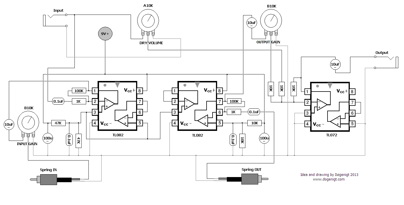
I am still in doubt about how to approach this - my goal is clear though: connect the cables from the "tape head" to an audio amp and be able to control the motors (stepper and spindle) as with the other drives.

This is a bit different though.
The spindle motor for spinning the disc is, as far as I am informed, driven off 400V. The stepper motor says 24V, and I've read 5V somewhere around the web. On the PCB, theres a traditional connector for floppy IDE ribbon cables.
The heads have nice accesible wires going the PCB, so it will be extremely easy to extend some wires to the audio amp! That way we can keep this antique piece of computer hardware intact.
Bigger is sometimes better, when it comes to hardware hacking!
Stay tuned!

Close-up of the heads with the wires.
PCB with nice big DIP ICs and large components!

søndag den 17. februar 2013

The Himalaya Spirit Photos

I did some experimentation with a rather new experimental film for Polaroid cameras which I got of The Impossible Project. I got 4 600-films which I wanted to bring to my trek in the Nepalese himalaya mountains last spring for some cool shots.
I guess the last pair of films weren't kept under optimal conditions so some of the critical chemicals involved in the developing of the images leaked or got twisted up in some way which resulted in these bizzare distortions and scrambling of the final images and I decided to name this series The Himalaya Spirit Photos.
I think they could go for some neat cover material or artwork for future releases or just Soundcloud images for various tracks. The weird repeating patterns on the last two images is some sort of chemical leakage which stuck to the rollers that sends out the instant picture and it was printed onto the image.