Viser opslag med etiketten aristoteles. Vis alle opslag

onsdag den 28. januar 2015

Aristoteles Logic Synth Update #5: Sequencer

I couldn't hold myself back after finishing the AND-gate module for dear Aristoteles so I dug up the schematic I drew for the 10-step sequencer module and jumped right in. In the video below I'll demonstrate how it works and the possibilities are vast! Combined with the AND-gates it's very convenient for creating melodies and patterns.


The sequencer is based on the '4017 CMOS Decade Counter' which counts from 0 to 9; adding 1 every time a clock pulse is received on the CLK input. It has 10 outputs going high/low one at a time depending on the current count. Only one output at a time can be high; the one corresponding to the count.
There's a reset pin which decides when the counter will reset to 0 so it's possible to have it count to any number below 9. I've implemented a rotary switch for setting the count from 9 to 0. If the reset pin is set to ground, the count limit will be set to 9 (default).

If an audio range signal is sent to the clock pin and one listens to one of the outputs, you get harmonic intervals when reducing the count limit. This makes sense as it only takes half the time to count to 5 instead of 10.
The frequency ratio to the frequency we get when counting to 10 (which can be seen as our fundamental) can be calculated by dividing 10 with the desired count. So the relation between i.e. 10 and 5 (10/5) is 2. We multiply our fundamental with this number to calculate the interval, which in this case would be an octave.
The chart below shows the intervals we get when we're adding the value of the fundamental - which is what happens every time we add a step for the counter. Interesting stuff!


Multiple of
fundamental
Ratio
within octave
Common name Hz and chroma
(Example)
1x 1/1 Fundamental 110 (A2)
2x 2/1 Octave 220 (A3)
3x 3/2 Perfect Fifth 330 (E4)
4x 4/2 Octave 440 (A4)
5x 5/4 Major Third 550 (C5)
6x 6/4 Perfect Fifth 660 (E5)
7x 7/4 Harmonic Seventh 770 (G5)
8x 8/4 Octave 880 (A5)
9x 9/8 Major Second 990 (B5)
10x 10/8 Major Third 1100 (C6)


As is the custom, I've attached the scheme for the circuit for this module. It's not that intricate, just LED's and output jacks on each output. I see that I forgot to add the transistor LED-drivers, but it's just as usual - look in the schematics for the other Aristoteles modules to see how they should be wired.
I've used a 12 position rotary switch for the reset switch, I couldn't find any 10-pos so 2 of the positions are grounded which just sets the count limit to 9 (all 10 steps). It can be tricky to find out which pins correspond to the switch positions but easy enough when using a multimeter for testing continuity between the output and the desired pin.

I will post all my stripboard layouts in a single package when I am finished with the last module :-)

 UPDATE 7/2-15:

My brother and I (as the duo SNU) had a really nice jam with the Aristoteles modules so far.  Here's a video of  our session when the sequencer was still on breadboard. I had my Clock Box (which also runs on 40106 and 4040 oscillators) control the power for the 4017 so a lot of modulations back and forth.


fredag den 5. september 2014

Aristoteles Logic Synth Update #3: Divider (simple)

The Aristoteles 'Lunetta' synth project is slowly but steadily going in the right direction. Here's the first of the two 4040 divider modules, demonstrated in the vid below.


Here's a scheme for the willing - simple and self-explanatory!

To explain this simple circuit in a simple way, it's taking any clock output from the other modules and counting 2^n times before setting the output HIGH - 2, 4, 8, 16 and so on - up to 2^12 times, that is 4096 clocks before setting the output high.

That's quite a division, so a high frequency is needed if one wants oscillations in the audio range. Otherwise it's great for turning audio range signals into LFO clocks. All in all, it's a very musical chip as it creates sub-octaves, which are relations of a factor of 2 to the input frequency.


I was flipping through Roads' Computer Music Tutorial one evening and began to read up upon the very first digital systems with flip-flop logic gates and discovered that the method of dividing down a master clock to acheive other tones is ancient! So-called 'divide-down tone synthesis' was discovered in 1930 so this method is almost a century old!

lørdag den 12. juli 2014

Aristoteles Logic Synth Update #2: Oscillators


The next module on the path of Aristoteles, the 'lunetta-style' synth, is finished! It's the central part of the synthesis: Oscillators. 8 of them. So essentially one could patch all 8 oscs into the 8-channel mixer and have 8 voice polyphony. They will also serve as the unique pseudo-CV clocks for the other modules, which is the main concept of CMOS-based synthesizers. The brain in all this is the classic 40106 chip, which is actually a logic NOT-gate flipping on and off. Below is a quick demo.


The oscillators have the following functions, as seen on the image to the right:
The first switch lets you choose if the osc should be constantly on or momentary, determined by the red button. This allows one to use the synth as a simple keyboard with a little willpower.

Next switch allows you to add extra capacitance to the oscillator, thereby setting the frequency range. The middle position of the switch is actually an off-position so the oscillator runs on the "offset cap" which is too small at the moment, so the frequency is very high. I wanted to have this range-switch so I could go with a potentiometer value around 100K for the frequency knob. This makes it easier to tune it without too big steps, as one gets if running on 1M or something in that range.

I chose to have the whole synth only producing square waves, to have it ultra lo-fi and simple. But I  thought it could be nice to at least have PWM for each osc though, so this is what we have below the freq pot.
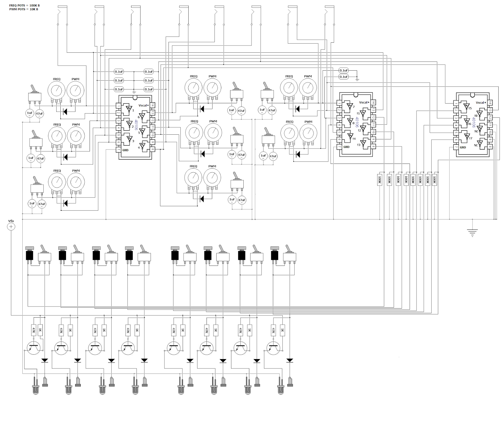
 It's a simple diode technique for adjusting pulse width of the wave, but I discovered that it was actually an inverse PWM, for what I wanted. It was setting the lenght of the off-time, not the on-time, so the LED's would be constantly on, only turning off for a short time, so I used another 40106 to inverse the HIGH/LOW order. This is the reason for 3 of the chips in the design - 2 IC's for getting 8 oscs and another one plus the leftover gates from IC 2 to have the pulses inversed.

The LED's are switched on and off with the help of transistors, to minimize voltage drop on the outputs. All the outputs are grounded with 100K resistors as well to prevent frying the chip if you touch the banana jacks.

Here's my quick and dirty schematic drawn in MS paint :)
Feel free to use it for inspiration in your own designs.

fredag den 23. maj 2014

Aristoteles Logic Synth Update #1: MIXER

Oh what a spring it's been! I was bedridden for about a month which really zapped all my creativity and I've slowly recovered now to bring back my mind on what is the icing on my cake of life: electronic gadgeting.

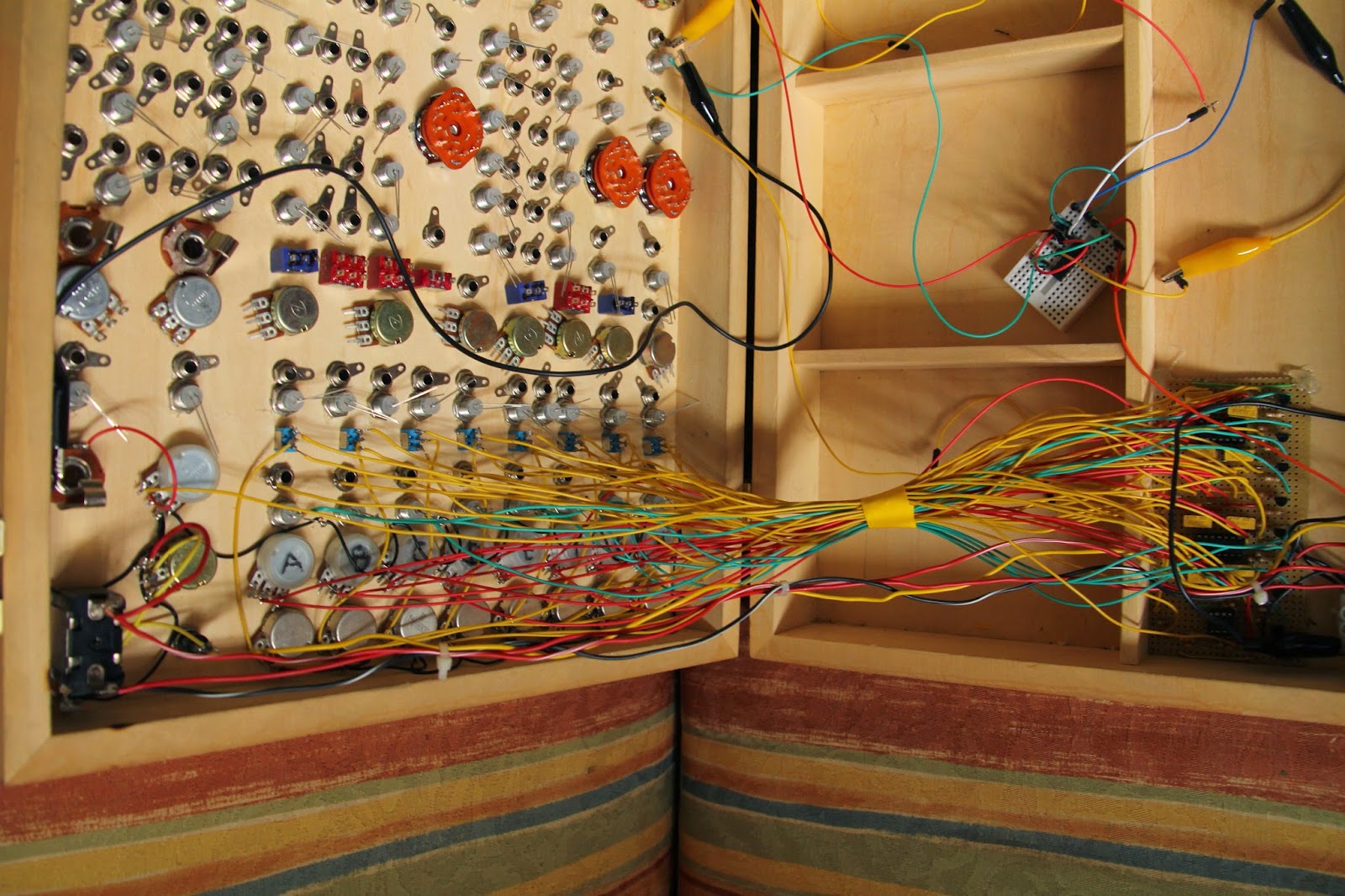
So just around New Years Eve I posted a picture of my newly assembled modular synth casing - no intestines yet though! But just before my bed claimed me for a minor lifetime, I was able to finish up the first and central part of the system: the 8-channel mixer with simple BP/LP filters + power supply.

Here's a demonstration of what I am talking about:


So the idea is that you have 8 channels in the mixer which are summed together after they've passed the filter circuit and the respective volume knob. When using stackable banana-jacks one might ask why bother with a multi-channel mixer; why not just stack 'em on top of each other and using passive resistor/diode mixing?
The problem for me was that mixing with just resistors would cause each output from every oscillator to drop in voltage and maybe cause instability with edge-detection in the chips they would enter - and diodes make distinctive modulation when used for summing. Which is why every output enters a diode, so it's still possible to mix signals together in a single mixer channel if one is running low on free channels. Other than that, diodes make sure that no cross-talk occurs if stacked for multiple operations.


Some pics:


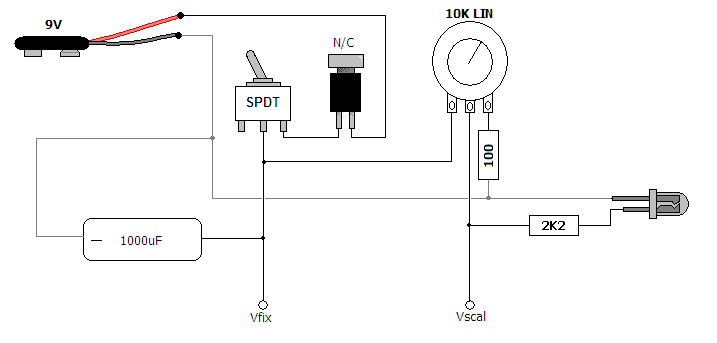
The power supply was super simple, just a power switch and momentary N/C button to switch on  and off and discharge the 470uF cap to get the power starve effect. Starving only affects the CMOS-chips used for sound generation, the mixer circuit isn't affacted by the variable supply voltage.
I will discuss the other modules in future entries and here's some schemes for the willing.


tirsdag den 31. december 2013

See you in 2014!

Dear readers, thank you so much for showing interest in my projects - I can't wait to show off all the coming projects I've got up my sleeve for you! Here's a snapshot of my largest project so far: ARISTOTELES! It's going to be a "logic" modular synth. I couldn't wait any longer with revealing it, I've just attached all the knobs and jacks to the box - stay tuned, happy new year and see you in 2014! best wishes, Dögenigt.