My friend Carl Dimsos has designed a nifty way to make sure you don't forget to turn off your hot soldering iron, so he made this Solder Timer (danish: lodde-timer) with a small ATtiny85 microprocessor, basically a very small version of your beloved Atmega (DIP) chip you find in the arduino.
The potentiometer sets the count-down time before the USB-power to the power socket gets turned off. The switch below resets the timer/turns it on or off. LED's are indicating whether the power to the socket is on or off.
Solder timer with soldering iron
The timer
Intestines
I am very pleased with the finish and I love this tool for our workshop! It's so convenient just to push a switch to turn on your soldering iron instead of fumbling with the power cord every time.
You can get the Solder Timer Kit from DimsOs - they have a webpage dedicated to this project on dimsos.dk/loddetimer/
You can obtain the pre-programmed ATtiny85 from DimsOs. The usb-power socket might be a bit tricky to get your hands on outside Denmark, but maybe eBay. If not, write me and I will help out.
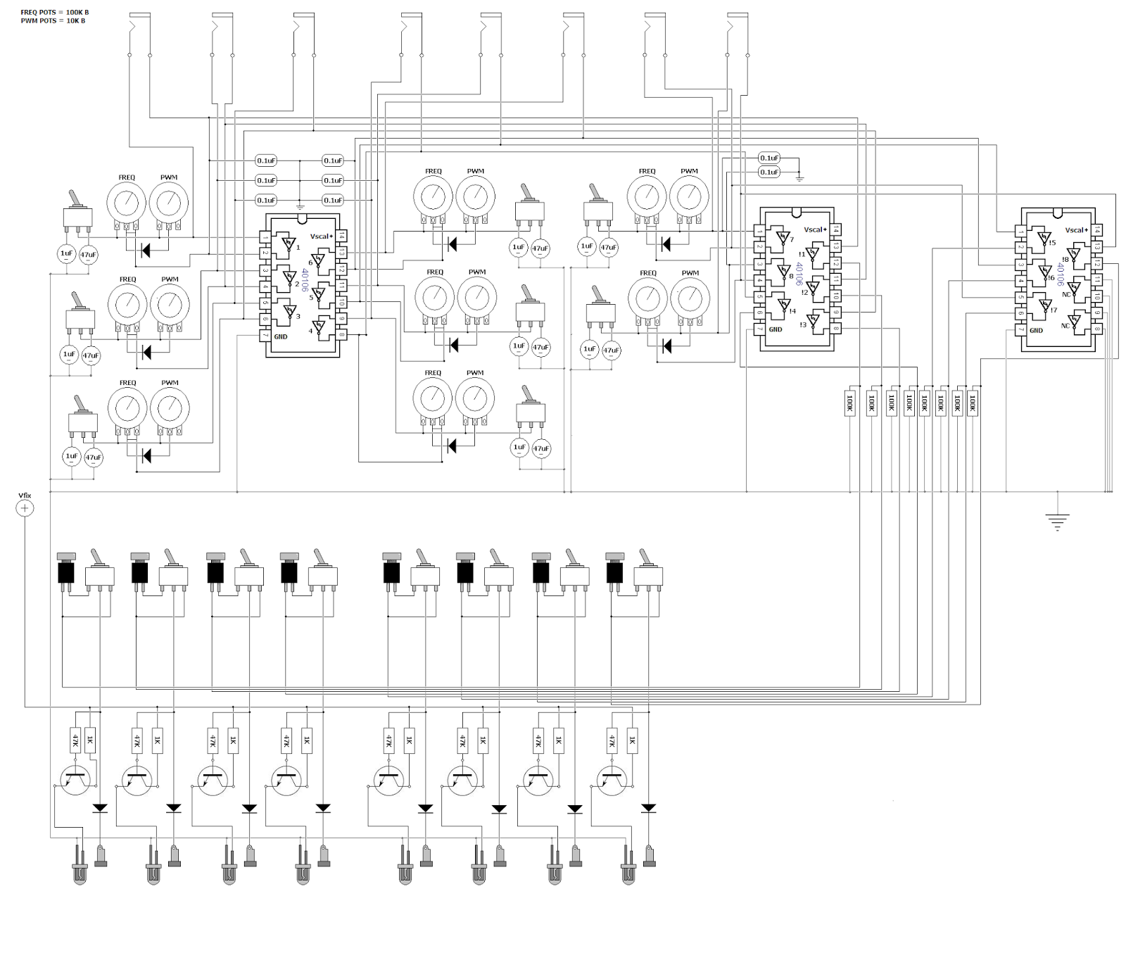
The next module on the path of Aristoteles, the 'lunetta-style' synth, is finished! It's the central part of the synthesis: Oscillators. 8 of them. So essentially one could patch all 8 oscs into the 8-channel mixer and have 8 voice polyphony. They will also serve as the unique pseudo-CV clocks for the other modules, which is the main concept of CMOS-based synthesizers. The brain in all this is the classic 40106 chip, which is actually a logic NOT-gate flipping on and off. Below is a quick demo.
The oscillators have the following functions, as seen on the image to the right:
The first switch lets you choose if the osc should be constantly on or momentary, determined by the red button. This allows one to use the synth as a simple keyboard with a little willpower.
Next switch allows you to add extra capacitance to the oscillator, thereby setting the frequency range. The middle position of the switch is actually an off-position so the oscillator runs on the "offset cap" which is too small at the moment, so the frequency is very high. I wanted to have this range-switch so I could go with a potentiometer value around 100K for the frequency knob. This makes it easier to tune it without too big steps, as one gets if running on 1M or something in that range.
I chose to have the whole synth only producing square waves, to have it ultra lo-fi and simple. But I thought it could be nice to at least have PWM for each osc though, so this is
what we have below the freq pot.
It's a simple diode technique for
adjusting pulse width of the wave, but I discovered that it was actually
an inverse PWM, for what I wanted. It was setting the lenght of the
off-time, not the on-time, so the LED's would be constantly on, only
turning off for a short time, so I used another 40106 to inverse the
HIGH/LOW order. This is the reason for 3 of the chips in the design - 2
IC's for getting 8 oscs and another one plus the leftover gates from IC 2
to have the pulses inversed.
The LED's are switched on and off with the
help of transistors, to minimize voltage drop on the outputs. All the
outputs are grounded with 100K resistors as well to prevent frying the
chip if you touch the banana jacks.
Here's my quick and dirty schematic drawn in MS paint :)
Feel free to use it for inspiration in your own designs.