onsdag den 12. november 2014

Audiovisual concerts: Plasma globe and 'TV light-to-sound effect'

Hi guys, I've been busy preparing for a couple of live shows I've been doing over the last month or so. I've been really into the idea of having an electromagnetic source translate into both light and sound at the same time as to have it as an audiovisual mini-installation on stage.

First experiment I wanted to test out was to "read" the video signal from a small monochrome CRT TV with a photocell (just wire a jack plug onto an ordinary solar cell or what have you) and having played around with translating sound to light with these small TV's I thought I wanted to try and combine both of these:
converting sound -> light and from light -> sound again! Kind of like a CRT-TV effects pedal of some sort.

I explain it all in the video beneath but I am using both a regular B/W TV where I send a sound signal into the composite video port which shows up on the screen as horizontal lines flickering in synch with the audio and then I tried with one of my TV-oscilloscopes and a photcell as well. The result is surprisingly interesting as it resembles the original signal quite a lot but still alters it in a distorted, fuzzy, gated kinda way.


I am thinking of developing the TV with a small board before the TV to adjust the signal in various ways, could be really neat! But already you have the brightness and contrast knobs with which you can make the sound only appear on the screen when it reaches a certain intensity level bright enough for the solar cell to detect it, thus making some gating mechanism.

Here's a concert I played in a cold war bunker here in Aarhus. I brought both TV's along together with my sampler, my cacophonator and greeting card sampler to be able to mix various signals to be sent into the TV's. Tye sampler spew out a weird bleeping sound for every clock for its step sequencer so I had to switch over to dry signal with that. I've learned a fair share of do's and don'ts since the first gig with this setup! :-)
Here's a small clip from the concert - event was called 'DIEM Elektro: Isolated Space')


Simultaneously I'd been exploring the wonders of electromagnetic induction coils for picking up various "hidden sounds" in electronic equipment and one night at my rural summmers house I had the pleasure of toying around with my brothers large plasma globe and thought it could be insane to eavesdrop to a plasma globe with the coil. Got a very cheap usb/5v-powered one and the sounds it spurts out through the coil is just heavenly! Such a pure electronic signal, striaght from the source :-)


This one I also  plan to evolve into an actual instrument with controls for all kinds of stuff, power supply and modulating the frequency of the coil and os on - lot's to come in the future! Here's a concert where I use the plasma ball "synth" - the sound might not do it much justice as my sampler was filled to burst with weird organic noise samples.


Thanks for looking, hope it sparked some inspiration in you - I myself couldn't help but to send dear Dr. Tesla a thought every once in a while listening and looking to the zapping electrodes of the plasma globe 3:-)

fredag den 26. september 2014

Solder Timer

My friend Carl Dimsos has designed a nifty way to make sure you don't forget to turn off your hot soldering iron, so he made this Solder Timer (danish: lodde-timer) with a small ATtiny85 microprocessor, basically a very small version of your beloved Atmega (DIP) chip you find in the arduino.
The potentiometer sets the count-down time before the USB-power to the power socket gets turned off. The switch below resets the timer/turns it on or off. LED's are indicating whether the power to the socket is on or off.
Solder timer with soldering iron
The timer
Intestines
I am very pleased with the finish and I love this tool for our workshop! It's so convenient just to push a switch to turn on your soldering iron instead of fumbling with the power cord every time.

You can get the Solder Timer Kit from DimsOs - they have a webpage dedicated to this project on dimsos.dk/loddetimer/
You can obtain the pre-programmed ATtiny85 from DimsOs. The usb-power socket might be a bit tricky to get your hands on outside Denmark, but maybe eBay. If not, write me and I will help out.

Carl's Prototype Timer
Vero board layout
Schematics

fredag den 12. september 2014

Composition for Acoustic Sequencer

I was invited by Acoustic Sequencing to make a composition for their installation called 'Galathea', which is a camping wagon filled with electric motors hitting on the interior and various instruments inside.
They are powered by an arduino with a power relay shield - controlled by Max, turning MIDI notes into serial commands.

My composition in the demo video below I chose to call 'Polterwagen' inspired by a poltergeist possessing an entire house and making noise with the interior. A better recording should come soon, this is just a promo for those who can make it to Aarhus Sound Festival 2014 this weekend where Galathea is installed.


It was good fun to compose for a "robot orchestra", trying out the different notes in the sequencer to see which note I should press to trigger a certain motor. With Polterwagen I was sort of pushing the limits of the equipment. The "drumkit" consists of motors hitting on a seat, a tin can, a spring and opening the fridge door! Then there are numerous motors on a xylophone and a child piano. There's also a note controlling a smoke machine and the fire alarm has been hacked as to play melodies. Very balstyrical project!

Solenoids on xylophone
Polter-piano!
Solenoid hitting on spring

fredag den 5. september 2014

Aristoteles Logic Synth Update #3: Divider (simple)

The Aristoteles 'Lunetta' synth project is slowly but steadily going in the right direction. Here's the first of the two 4040 divider modules, demonstrated in the vid below.


Here's a scheme for the willing - simple and self-explanatory!

To explain this simple circuit in a simple way, it's taking any clock output from the other modules and counting 2^n times before setting the output HIGH - 2, 4, 8, 16 and so on - up to 2^12 times, that is 4096 clocks before setting the output high.

That's quite a division, so a high frequency is needed if one wants oscillations in the audio range. Otherwise it's great for turning audio range signals into LFO clocks. All in all, it's a very musical chip as it creates sub-octaves, which are relations of a factor of 2 to the input frequency.


I was flipping through Roads' Computer Music Tutorial one evening and began to read up upon the very first digital systems with flip-flop logic gates and discovered that the method of dividing down a master clock to acheive other tones is ancient! So-called 'divide-down tone synthesis' was discovered in 1930 so this method is almost a century old!

tirsdag den 12. august 2014

Compositions on Bandcamp

Hi lovely people! Hope you're enjoying your summer.
I've created a bandcamp store where you can get some of my releases in lossless format.
Some of the compositions might appear on a future debut album, which I intend to release online and on a physical medium which will be quite different from your typical CD/LP format.

Link to my bandcamp is found by clicking on 'Releases' in the top menu.

The latest track I've finished is called Plate Phonetics and consists of recordings of cuts and scratches on blank phono records which gives weird rhytmic patterns. On top of it I've added some tones with feedback oscillator (Derek Holzer's soundbox) and recording of my homemade string instrument.


The other tracks available so far, you might've heard on my soundcloud. They are 'Subtlle Visit' composed during a meditation and creativity workshop with Kim Cascone and 'Veins of The Robot' composed with Christina Kubisch during a workshop with her on DIEM where we brought her electromagnetic headphones in the city of Aarhus.
'Entraining Patterns' is made solely from homemade equipment: the wavetable synth, Vibrati Punk Console and passive ring mod. There's also a composition made with The MicroWaveSampler.

lørdag den 12. juli 2014

Aristoteles Logic Synth Update #2: Oscillators


The next module on the path of Aristoteles, the 'lunetta-style' synth, is finished! It's the central part of the synthesis: Oscillators. 8 of them. So essentially one could patch all 8 oscs into the 8-channel mixer and have 8 voice polyphony. They will also serve as the unique pseudo-CV clocks for the other modules, which is the main concept of CMOS-based synthesizers. The brain in all this is the classic 40106 chip, which is actually a logic NOT-gate flipping on and off. Below is a quick demo.


The oscillators have the following functions, as seen on the image to the right:
The first switch lets you choose if the osc should be constantly on or momentary, determined by the red button. This allows one to use the synth as a simple keyboard with a little willpower.

Next switch allows you to add extra capacitance to the oscillator, thereby setting the frequency range. The middle position of the switch is actually an off-position so the oscillator runs on the "offset cap" which is too small at the moment, so the frequency is very high. I wanted to have this range-switch so I could go with a potentiometer value around 100K for the frequency knob. This makes it easier to tune it without too big steps, as one gets if running on 1M or something in that range.

I chose to have the whole synth only producing square waves, to have it ultra lo-fi and simple. But I  thought it could be nice to at least have PWM for each osc though, so this is what we have below the freq pot.
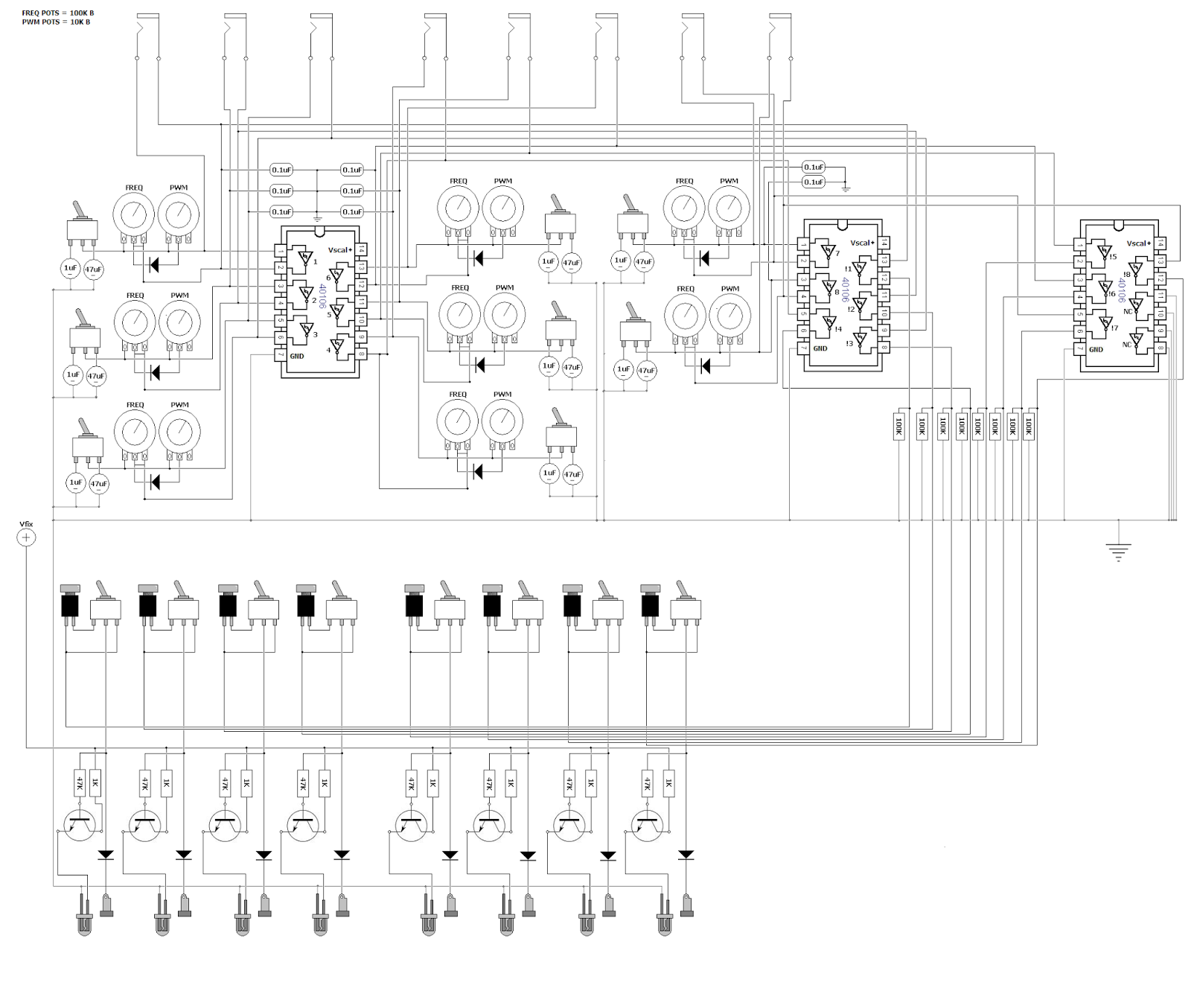
 It's a simple diode technique for adjusting pulse width of the wave, but I discovered that it was actually an inverse PWM, for what I wanted. It was setting the lenght of the off-time, not the on-time, so the LED's would be constantly on, only turning off for a short time, so I used another 40106 to inverse the HIGH/LOW order. This is the reason for 3 of the chips in the design - 2 IC's for getting 8 oscs and another one plus the leftover gates from IC 2 to have the pulses inversed.

The LED's are switched on and off with the help of transistors, to minimize voltage drop on the outputs. All the outputs are grounded with 100K resistors as well to prevent frying the chip if you touch the banana jacks.

Here's my quick and dirty schematic drawn in MS paint :)
Feel free to use it for inspiration in your own designs.

mandag den 30. juni 2014

The 'MAXIMUX controller': High-res controller for Max/MSP (Update #1)


Nerd Alert! My favourite g33k-buddies (Carl Dimsos and Gus the Friendly Giant) and I are at it again! For a while, we've been discussing ways to interact with Max in a fast and precise way. The project is going to be a controller in a suitcase, armed with an Atmega-chip and a MUX-shield which allows us to have 48 analog inputs speaking with the arduino! This will give us a 10-bit resolution on all analog readings which is suitable for controlling audio parameters in Max. I want to have a lot of different and expressive sensors and knobs n butts for varying the input voltages. 
´

So far I have whole lot of scrap parts from old helicopter remote controls and sensors sensing touch, distance, humidity, light intensity, gyroscopic motion and a lot more.
I've also disassembled two flight simulator joysticks with their own respective D/A-converters, which gives me 7 more analog inputs with 16-bit resolution!

I decided to have this project be a classical aim for those who's spent decades creating music in front of a computer monitor: to have the laptop lid closed and have all the paramters transfered to the controller.
For receiving  feedback from Max I am going to use a 16x2 LCD display, as seen on The MicroWaveSampler (another arduino project done with Dimsos) for getting the values from the inputs and the max-paramter assigned to it. But I wanted to be able to see a little bit more of what's going on inside so I found an arduino project called Chibimo which allows the user to have a 128x64 display as an external monitor. (only winXP, sorry)
I've already tested it out, narrowing my patches way down to 128 pixels wide to have it fit on the little screen. I will use a usb-numpad to skip around in the patch to show different parts on the LCD monitor. More to come! Stay tuned and thanks for following guys.

fredag den 23. maj 2014

Aristoteles Logic Synth Update #1: MIXER

Oh what a spring it's been! I was bedridden for about a month which really zapped all my creativity and I've slowly recovered now to bring back my mind on what is the icing on my cake of life: electronic gadgeting.

So just around New Years Eve I posted a picture of my newly assembled modular synth casing - no intestines yet though! But just before my bed claimed me for a minor lifetime, I was able to finish up the first and central part of the system: the 8-channel mixer with simple BP/LP filters + power supply.

Here's a demonstration of what I am talking about:


So the idea is that you have 8 channels in the mixer which are summed together after they've passed the filter circuit and the respective volume knob. When using stackable banana-jacks one might ask why bother with a multi-channel mixer; why not just stack 'em on top of each other and using passive resistor/diode mixing?
The problem for me was that mixing with just resistors would cause each output from every oscillator to drop in voltage and maybe cause instability with edge-detection in the chips they would enter - and diodes make distinctive modulation when used for summing. Which is why every output enters a diode, so it's still possible to mix signals together in a single mixer channel if one is running low on free channels. Other than that, diodes make sure that no cross-talk occurs if stacked for multiple operations.


Some pics:


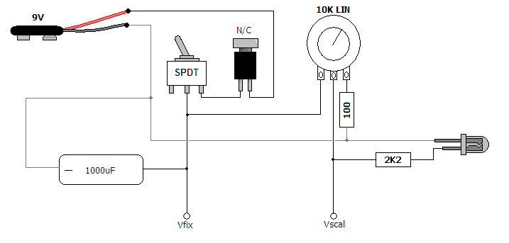
The power supply was super simple, just a power switch and momentary N/C button to switch on  and off and discharge the 470uF cap to get the power starve effect. Starving only affects the CMOS-chips used for sound generation, the mixer circuit isn't affacted by the variable supply voltage.
I will discuss the other modules in future entries and here's some schemes for the willing.


tirsdag den 21. januar 2014

Greeting Card Sampler Boxed

I finally got to finish up my project seen in this previous post: Voice Message Greeting Cards turned into Lo-Fi Sampler. It's the 'voice message recordable greeting card' I hacked into a small looper with playback speed bend, now in a neat little encasing I found in a thrift shop. I think it's a intercom from the 70's, quite nice.


The video shows the features which are: potentiometer for varying the playback speed, switch for selecting loop mode, red button on the side is for restarting the device, which re-triggers the message, switch for selecting between the inputs - electret mic or input jack, jack for sending output to an amplifier and in the bottom are two banana jacks which allows you to control the device with a vactrol or light sensor, or any other resistive sensor :)


I had a very nice day at the FabLab's Maker's Day in Copenhagen, where I held a small symposium and a koncert with my current setup. One of the guys from CEO Bendorama who also played, got a recording of my concert - which includes the Greeting Card Sampler. (Thanks John!)