Viser opslag med etiketten eurorack. Vis alle opslag

onsdag den 11. november 2020

Eurorack Modules: DIY CRT scope

Hi guys, I know it's been a while.
I've fallen behind with updating my blog although I've been active on my facebook and my YouTube pages. Sometime back in 2018 I decided to switch to eurorack as my DIY stuff required a lot of maintenance. I uploaded this video of my current studio recorded with an old crappy camcorder where you get the general idea of the setup:


I've bought several weird modules which sort of fits into my previous aesthetic with vero test-boards, bendable CMOS-chips, tube-amplifiers, CV-controllable tape-player, nixie tube counter and a custom built CRT-scope module I designed in collaboration with a tinkerer from Belarus under the name Ghetto Hacker. 

I stumbled upon this Ghetto Hacker guy where I saw he'd built a module for eurorack with a small CRT from a camcorder, used as an oscilloscope. I paid him for his time and skills to make me one and the result is really amazing, sturdy 3d-printed arm to hold everything in place and a nice black front plate.
 
Here's some video:

Ghetto Hacker's finished work:
 
 
Testing module in my own case:

 
 And here's some pix from the build:

Blueprint for mounting
Layout for front plate
Front Plate done!
CRT installed
Under construction
Finished module installed

If you're interested to see what I'm up to, go follow me on YouTube (Dani Dogenigt) or find Dogenigt on facebook. I think I am going to give a guided tour of my eurorack system so you can see some of the modules in action. Please take care and see you soon!

torsdag den 6. august 2015

DIY Modular #1: Wooden case and CRT-monitors.

Hola amigos y amigas! :-)

Besides enjoying a long summer holiday, before starting on my master's degree in electronic music,
I've been rethinking my entire setup and decided to abandon the idea of having lots of separate boxes which I have to arrange and connect for every concert and instead jump on the modular wagon but with my own standards and designs.
(no "eurocrack" ;-P )

I am going to design and build every module from scratch and include some different and unique modules and parts and try different methods of circuit designing. The frontplates are going to be transparent so all the insides are visible, which adds an extra dimension the the machine - it will be an work of art, from circuit to interface.

I wanted something organic and easy to work with so I went with wooden frames for the cases and for the front- and backplates I chose transparent acrylic glass as it's neat to be able to see the insides of the machine. I will put a lot of emphasis on the aesthetics of the circuits, parts and components because of this. For attaching the acrylic frontplates I am going to use an alu-rail with rectangular 'slide nuts' as the width of the modules will vary.
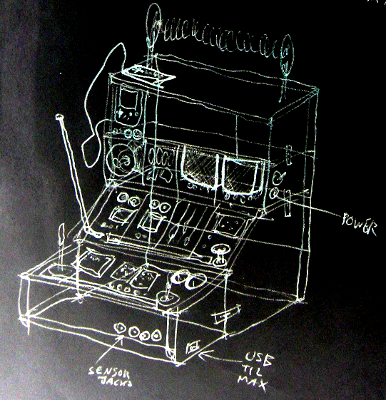
In the future I want to be able to expand with further identical cases on top so I added a mechanism for attaching the frames to each other. The drawing above shows my vision of what the machine will ultimately end up looking like.

Some snaps of the cases / frames:
Wooden frames with plexi back plate

Single frame / case

Both frames attached

I found it crucial to start with the design of the power supply part. I had an old PSU from a laptop lying around - 19V DC with app. 5A of juice to play around with. Some of the parts will be quite power-hungry so in the future I might have to step it up to 10A. I found a cute old capacitor from Denmark and decided to use it as stabilizing cap. My plan is to have most of the modules run on  ±12V but I might add a 5V line as well but so far I've been using LM317 variable voltage regulators for each device.
Power connector and switch w/ LED
Rear view - large capacitor added
Personal notes on PSU

The first actual modules will be a 'terminal' with a green-monochrome CRT TV. It will receive a video signal from an Atmega328 generating simple text strings with data such as the temperature inside the box, total run time, date and time and a lot of other stuff.
Next to it another CRT TV of the same size will display the master stereo output as a simple oscilloscope. Beneath the TV I will install two analog VU meters with a nice warm backlight as well.

Shelf for the TV's and front plate test
Side view of the shelf
Rear view of the CRTs
Both TVs turned on!
VU meters on as well. :-)
Startup-text generated by the arduino
An analog current panel meter will be beneath the terminal showing the power usage for alle the modules. Each TV draws around 1000 mA but so far 5A in total should be enough. I've used 7812 regulators for each TV to supply 12V but the regulators turn very very hot and will shut off without proper cooling so I had to mount rather large heatsinks.
The plan is to mount front plates in front of the TV's and have all the knobs and in/outputs controlling the TV and the terminal.

For labels I want every front plate etched with a CNC router (or just by hand?) and then edge-light it with an LED-strip installed beneath the acrylic. A test looks like this (scrap acrylic with scratches):
LED-strip test
Edge-lighting test
Edge-lighting test