lørdag den 12. juli 2014

Aristoteles Logic Synth Update #2: Oscillators


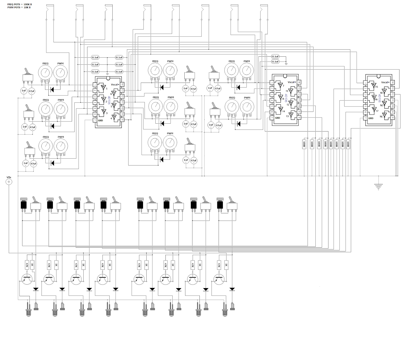
The next module on the path of Aristoteles, the 'lunetta-style' synth, is finished! It's the central part of the synthesis: Oscillators. 8 of them. So essentially one could patch all 8 oscs into the 8-channel mixer and have 8 voice polyphony. They will also serve as the unique pseudo-CV clocks for the other modules, which is the main concept of CMOS-based synthesizers. The brain in all this is the classic 40106 chip, which is actually a logic NOT-gate flipping on and off. Below is a quick demo.


The oscillators have the following functions, as seen on the image to the right:
The first switch lets you choose if the osc should be constantly on or momentary, determined by the red button. This allows one to use the synth as a simple keyboard with a little willpower.

Next switch allows you to add extra capacitance to the oscillator, thereby setting the frequency range. The middle position of the switch is actually an off-position so the oscillator runs on the "offset cap" which is too small at the moment, so the frequency is very high. I wanted to have this range-switch so I could go with a potentiometer value around 100K for the frequency knob. This makes it easier to tune it without too big steps, as one gets if running on 1M or something in that range.

I chose to have the whole synth only producing square waves, to have it ultra lo-fi and simple. But I  thought it could be nice to at least have PWM for each osc though, so this is what we have below the freq pot.
 It's a simple diode technique for adjusting pulse width of the wave, but I discovered that it was actually an inverse PWM, for what I wanted. It was setting the lenght of the off-time, not the on-time, so the LED's would be constantly on, only turning off for a short time, so I used another 40106 to inverse the HIGH/LOW order. This is the reason for 3 of the chips in the design - 2 IC's for getting 8 oscs and another one plus the leftover gates from IC 2 to have the pulses inversed.

The LED's are switched on and off with the help of transistors, to minimize voltage drop on the outputs. All the outputs are grounded with 100K resistors as well to prevent frying the chip if you touch the banana jacks.

Here's my quick and dirty schematic drawn in MS paint :)
Feel free to use it for inspiration in your own designs.

mandag den 30. juni 2014

The 'MAXIMUX controller': High-res controller for Max/MSP (Update #1)


Nerd Alert! My favourite g33k-buddies (Carl Dimsos and Gus the Friendly Giant) and I are at it again! For a while, we've been discussing ways to interact with Max in a fast and precise way. The project is going to be a controller in a suitcase, armed with an Atmega-chip and a MUX-shield which allows us to have 48 analog inputs speaking with the arduino! This will give us a 10-bit resolution on all analog readings which is suitable for controlling audio parameters in Max. I want to have a lot of different and expressive sensors and knobs n butts for varying the input voltages. 
´

So far I have whole lot of scrap parts from old helicopter remote controls and sensors sensing touch, distance, humidity, light intensity, gyroscopic motion and a lot more.
I've also disassembled two flight simulator joysticks with their own respective D/A-converters, which gives me 7 more analog inputs with 16-bit resolution!

I decided to have this project be a classical aim for those who's spent decades creating music in front of a computer monitor: to have the laptop lid closed and have all the paramters transfered to the controller.
For receiving  feedback from Max I am going to use a 16x2 LCD display, as seen on The MicroWaveSampler (another arduino project done with Dimsos) for getting the values from the inputs and the max-paramter assigned to it. But I wanted to be able to see a little bit more of what's going on inside so I found an arduino project called Chibimo which allows the user to have a 128x64 display as an external monitor. (only winXP, sorry)
I've already tested it out, narrowing my patches way down to 128 pixels wide to have it fit on the little screen. I will use a usb-numpad to skip around in the patch to show different parts on the LCD monitor. More to come! Stay tuned and thanks for following guys.

fredag den 23. maj 2014

Aristoteles Logic Synth Update #1: MIXER

Oh what a spring it's been! I was bedridden for about a month which really zapped all my creativity and I've slowly recovered now to bring back my mind on what is the icing on my cake of life: electronic gadgeting.

So just around New Years Eve I posted a picture of my newly assembled modular synth casing - no intestines yet though! But just before my bed claimed me for a minor lifetime, I was able to finish up the first and central part of the system: the 8-channel mixer with simple BP/LP filters + power supply.

Here's a demonstration of what I am talking about:


So the idea is that you have 8 channels in the mixer which are summed together after they've passed the filter circuit and the respective volume knob. When using stackable banana-jacks one might ask why bother with a multi-channel mixer; why not just stack 'em on top of each other and using passive resistor/diode mixing?
The problem for me was that mixing with just resistors would cause each output from every oscillator to drop in voltage and maybe cause instability with edge-detection in the chips they would enter - and diodes make distinctive modulation when used for summing. Which is why every output enters a diode, so it's still possible to mix signals together in a single mixer channel if one is running low on free channels. Other than that, diodes make sure that no cross-talk occurs if stacked for multiple operations.


Some pics:


The power supply was super simple, just a power switch and momentary N/C button to switch on  and off and discharge the 470uF cap to get the power starve effect. Starving only affects the CMOS-chips used for sound generation, the mixer circuit isn't affacted by the variable supply voltage.
I will discuss the other modules in future entries and here's some schemes for the willing.


tirsdag den 21. januar 2014

Greeting Card Sampler Boxed

I finally got to finish up my project seen in this previous post: Voice Message Greeting Cards turned into Lo-Fi Sampler. It's the 'voice message recordable greeting card' I hacked into a small looper with playback speed bend, now in a neat little encasing I found in a thrift shop. I think it's a intercom from the 70's, quite nice.


The video shows the features which are: potentiometer for varying the playback speed, switch for selecting loop mode, red button on the side is for restarting the device, which re-triggers the message, switch for selecting between the inputs - electret mic or input jack, jack for sending output to an amplifier and in the bottom are two banana jacks which allows you to control the device with a vactrol or light sensor, or any other resistive sensor :)


I had a very nice day at the FabLab's Maker's Day in Copenhagen, where I held a small symposium and a koncert with my current setup. One of the guys from CEO Bendorama who also played, got a recording of my concert - which includes the Greeting Card Sampler. (Thanks John!)

tirsdag den 31. december 2013

See you in 2014!

Dear readers, thank you so much for showing interest in my projects - I can't wait to show off all the coming projects I've got up my sleeve for you! Here's a snapshot of my largest project so far: ARISTOTELES! It's going to be a "logic" modular synth. I couldn't wait any longer with revealing it, I've just attached all the knobs and jacks to the box - stay tuned, happy new year and see you in 2014! best wishes, Dögenigt.


mandag den 16. december 2013

Live concert in cold war dome bunker

This autumn, several empty or unused spaces in Aarhus were turned into cultural platforms, amongst them were a minor cold war dome bunker where artists from DIEM were invited to perform a handful of intimate concerts for a small crowd. The event collided perfectly with the finalizing of my MicroWaveSampler - so my setup consisted of that, my Microcassette Tape Delay and my Spring Reverb Module. I borrowed my brother's GoPro Cam to record the concert from my POV.


Concert program folder showing inside of the dome

I'd recorded a sample bank for the MWS from instruments and other acoustic sources in my studio (the same samples used in this track) which brought a strange shamanistic and mystical vibe into the bunker. The lower frequencies, mostly from the shaman's drum-samples, resonated quite a lot in the room which you can hear in the video.
I didn't bother to tame the spectrum, I knew the room would be quite unique with some heavy room modes so I chose to embrace this and get a natural communion going with the dome. Improvising was nice because it allowed me to adjust to the surroundings.


Snapshot of my setup


I brought my crappy behringer mixer to be able to control the signal path and mix between dry/wet. But basically the main sources were the (microwave)sampler and a simple contact-mic bass-guitar which were sent to the mixer and then sent via a 'send' channel to the Tape Delay, back into the mixer and via the other send channel to the spring reverb. The reverb has dry/wet control built in so I could control the amount of reverb - which was convenient at times as the spring started oscillating very easily. I enjoyed the concert a lot, and it was quite exciting to perform with this setup!

søndag den 6. oktober 2013

The MicroWaveSampler!

It is with great joy I am able to present to you: our dearest little newborn, The MicroWaveSampler.
An Arduino/Adafruit WaveShield-based 'Lo-Fi' Sampler with 16-step sequencer, preset function and external clock.
A project between my best g33k-buddy Carl @ DimsOs and I, which has been underway for a year.
We chose to call it MicroWaveSampler because it's a Microprocessor-driven Wave-sound Sampler.

Here it is in action, bellow we'll dive into the intestines.


I bought the Wave Shield some years ago and always wanted to make some simple sampler from it - I was thinking something very mechanical with rotary switches but as Carl made me aware of, the ATMega328 IC holds great potential for internally taking care of all sequencing and triggering of the samples on the card.
This awareness was the first step on the path to creating a fully functional sampler with the arduino. It turned out that we had to be very creative not only with the programming but also physically and circuit-wise, making the most of the fairly limited microprocessor IC. On the layout below, you can see the physical concept of the constellation:


So the brain of the game is of course our microprocessor, the Atmega328. It reads the WAV-files from the SD-card. We have a GUI in our little 16x2 LCD which shows our 16 steps/samples on the bottom line, each soundfile on the card is assigned a unique ASCII character, and since it's a chinese LCD we're using we have 185 symbols available (minus the ones we are using for common indicators etc).

For selecting steps and step menus (functions) we've built arrays of pushbuttons going through R2R-ladders, which means that each button sends a unique voltage to one of the AIN's on the atmega. The video shows how this is implemented but you select the step you want to edit and set the sample #, the sample rate and muting

Stripboard layout
For our "rotary encoder", we had to be creative as we were in need of a pin because of the display and the DAC, so we decided to use a DC-motor as our 'select-wheel', so just one AIN reads the voltage coming from the motor - if we spin it right, the reading is positive, spin it left and the reading is negative. That way we can determine which direction the motor is being spinned.

There's a knob for adjusting the internal clock (metronome) speed and one can switch to the external clock to syncronize with other devices. We've implemented a little button in the lower right corner for manual clocking if one doesn't have his Clock Box at hand.

Last but not least, the microprocessor sends the data to the DAC, which converts it to analog signals, amplified and sent to the audio jack.

We thought it was a good idea to go ahead and get the whole thing soldered together before engaging in the programming process. So we designed a stripboard layout and soldered everything together.
Actually we wanted to have the everything on a single stripboard, but as I already had my Wave Shield soldered up, we decided to use that and make pin headers for the shield which is nice because it saves quite a lot of space on the board. To have easier acces to the buttons while programming and testing we mounted everything in a cardboard test-box which made it look pretty sweet and silly :-)

Stripboard done
Wave Shield and LCD mounted
Everything soldered together

Now when the intestines where firmly put together, we could start experimenting with the software. It was without any doubt the most thrilling part of the whole process. To invent a small program for the machine and watch Carl code away for hours and hours. I am quite novice-level when it comes to programming so it was really a gift to have a skilled programmer design the brain for the device from my ideas. I would lay in bed before going to sleep getting new perspectives on how to implement the features needed and write them down on paper to show him so he could get an idea of how I wanted it to be.

The code will be available in the future, it still needs some polishing before it's ready for the public.

One of many code-nights @ DimsOs
Blueprint for program
Screenshot of the extensive code!
After 9 months or so, about as long as it takes to give birth to a little beauty like this, the horizon of completion came closer and it was time to get the thing boxed in it's proper casing. I got a obsolete television-channel box from my mother-in-law with a nice thin metal front-plate. I had MadsT, the the skilled carpenter and other half of DimsOs, help me drilling the holes in the frontplate. It required some delicate measuring to get the spacing between all the step-buttons right.

Casing Layout
Encased MWS!
Final Product
It's been such a learningful process and it really pays off to be persistent and patient: to be able to have a personal music device designed to fit your own basic needs.

In the future we plan to make a version 2.0 - the design will be quite different, not so unorthodox as this one. If everything goes right, we will be able to provide DIY-kits with these. I'll let you know!
As before-mentioned, the code will be up soon, I will update this thread when the time comes.
Feel free to write us, comment and share!


UPDATE October15h, 2013:

I did a recording session for the virgin concerts with the MWS, recording all sorts of concrete sounds in my lab, acoustic instruments and such. Made a multitrack session in Reaper with the beats, the result was pretty nice.

onsdag den 21. august 2013

Spring Reverb Module

After a nice long summer holiday with plenty of time for contemplation and relaxing, I felt it was time to return to the workshop and strike while the soldering-iron was hot so I finally finished my spring reverb module which had caused me some headaches during the spring time (no pun here). During trouble shooting, I've learned a lot about operational amplifiers which will be useful in future builds.

Here's the finalized contraption in action!


It's basically a Spring Reverb Tank (the ones you find in old guitar amps) for which I've made an amplifier-circuit. The 'IN' knob controls the gain for the signal sent into the spring, the 'DRY' knob lets through some of the clean signal to the internal mixer circuit and the 'WET' knob sets the gain for the signal from the spring tank to the mixer. This lets you just plug one jack-cable into the module and adjust how much of the clean signal you want to blend with the reverbed sound - saves a lot of cable mess. The input gain acts as a kind of "decay time" as it somewhat determines how long the spring will vibrate for because of the amplitude sent to the spring.

I also found out that you can get nice feeding oscillations if you turn off the input sound! (happens in the end of the video)


I feel this is kind of a 'must have, must build' module for anyone serious about having a handmade modular setup, so I was very determined to get this done and now I am so relieved about finally having this mo-fo boxed and good to go so I can focus on the larger projects I am about to unveil for you good folks out there!

Here's my scheme for the amplifier-circuit:


I chose to use seperate ICs to avoid bleeding of the signals, which I encountered on the test-board. I see that I didn't bias the mixing stage, but it sounds good without.