I've been busy with my undergraduate project on the conservatory but I've been spending my time fiddling with the LSDJ (Little Sound DJ) for Gameboy Classic / DMG - really fun and inspiring way to compose music! You've only got 4 channels to play with: 2 pulse oscillator channels, a wave/sample channel and a noise channel.
I enjoy making pseudo-covers with trackers so here's my first gameboy-track inspired by Xanthochroid's "Bipartisan Apostasy" Dimmu Borgir style ;-)
I just received this footage from the Noise Convention last year on Mayhem, Copenhagen. The video is not very long but there's audio recording from the mixer of the full concert if anyone's interested.
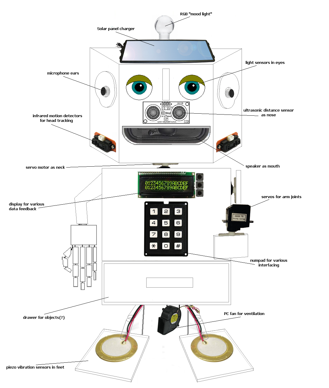
I want to show you a cute little side-project I am currently brewing on. It's going to be a robot with a
voice recognition shield for Arduino
(EasyVR 2.0 Shield). The idea is to have a fully functioning voice
controlled robot able to control power relays with motion tracking servo motors for the neck and arms.
Right now I am testing the voice recognition out with responds in both english and danish.
The final idea is shown in the drawing to the right. There will be a lot of challenges involved if I am going to realize all the ideas. I will need a little help from my friends.
I couldn't hold myself back after finishing the AND-gate module for dear Aristoteles so I dug up the schematic I drew for the 10-step sequencer module and jumped right in. In the video below I'll demonstrate how it works and the possibilities are vast! Combined with the AND-gates it's very convenient for creating melodies and patterns.
The sequencer is based on the '4017 CMOS Decade Counter' which counts from 0 to 9; adding 1 every time a clock pulse is received on the CLK input. It has 10 outputs going high/low one at a time depending on the current count. Only one output at a time can be high; the one corresponding to the count.
There's a reset pin which decides when the counter will reset to 0 so it's possible to have it count to any number below 9. I've implemented a rotary switch for setting the count from 9 to 0. If the reset pin is set to ground, the count limit will be set to 9 (default).
If an audio range signal is sent to the clock pin and one listens to one of the outputs, you get harmonic intervals when reducing the count limit. This makes sense as it only takes half the time to count to 5 instead of 10.
The frequency ratio to the frequency we get when counting to 10 (which can be seen as our fundamental) can be calculated by dividing 10 with the desired count. So the relation between i.e. 10 and 5 (10/5) is 2. We multiply our fundamental with this number to calculate the interval, which in this case would be an octave.
The chart below shows the intervals we get when we're adding the value of the fundamental - which is what happens every time we add a step for the counter. Interesting stuff!
Multiple of fundamental
Ratio within octave
Common name
Hz and chroma (Example)
1x
1/1
Fundamental
110 (A2)
2x
2/1
Octave
220 (A3)
3x
3/2
Perfect Fifth
330 (E4)
4x
4/2
Octave
440 (A4)
5x
5/4
Major Third
550 (C♯5)
6x
6/4
Perfect Fifth
660 (E5)
7x
7/4
Harmonic Seventh
770 (G5)
8x
8/4
Octave
880 (A5)
9x
9/8
Major Second
990 (B5)
10x
10/8
Major Third
1100 (C♯6)
As is the custom, I've attached the scheme for the circuit for this module. It's not that intricate, just LED's and output jacks on each output. I see that I forgot to add the transistor LED-drivers, but it's just as usual - look in the schematics for the other Aristoteles modules to see how they should be wired.
I've used a 12 position rotary switch for the reset switch, I couldn't find any 10-pos so 2 of the positions are grounded which just sets the count limit to 9 (all 10 steps). It can be tricky to find out which pins correspond to the switch positions but easy enough when using a multimeter for testing continuity between the output and the desired pin.
I will post all my stripboard layouts in a single package when I am finished with the last module :-)
UPDATE 7/2-15:
My brother and I (as the duo SNU) had a really nice jam with the Aristoteles modules so far. Here's a video of our session when the sequencer was still on breadboard. I had my Clock Box (which also runs on 40106 and 4040 oscillators) control the power for the 4017 so a lot of modulations back and forth.
I thought it was time for building the next module for dear Aristoteles, my 'lo-fi logic synth project' so I did the logic gate module which consists of 8 AND gates with 2 inputs and an LED for the output. The truth table on the right describes how the gate will behave: the output only goes high (1) when both inputs are high. The result is a very simple form of amplitude modulation, or it can be used to control the path of signals from the other modules with counters or LFO's, you name it.
The video below speaks for itself.
In the video I demonstrate the effect of the 3 different frequency ranges on the oscillators: LFO range signals are good for 'letting through' audio range signals at a certain rate for "beep beep beep beep" sounds. 2 audio range signals will generate complex pulsating modulations and beatings when adjusting the pulse width.
Setting the range to the high pitched setting on both oscillators will generate classic vintage radio-like modulation squeeks. I also tried using the 'octave divider module' for one of the inputs which has its own unique sound.
I chose to have all the logic gates as AND gates. For a long time I was in doubt about wether to have a pair of XOR or NAND gates just for the hell of it but I could not find a good reason as they don't do much sound-wise where as the AND gate is so clear in its function and I want to be able to make complex signal paths with counters, dividers, random clocks and all eight oscs - all controlling each other through the gates.
I am already starting on the 10-step counter 'cause I cannot wait to have each step 'open' a unique oscillator with different frequencies!
The circuit is very simple, I basically just wired the in- and outputs straight to the 4081 but attached 100K resistors on each pin to prevent static electricity from the end of the wires going into the chip when patching.
LED's are controlled by transistors as always to prevent voltage dropping on the outputs.
UPDATE:
I had my brother a.k.a. SNU over and he fell in love with the new module which resulted in hours of wiggling. Here's a a little peak of the tweak :-)
A late happy solstice to all of ye - I have been ind bed for most of the holidays, guess my body and mind was in need for some rest, it's hard work wanting to do you own thing and the following concert you are about to witness required a lot of planning and soldering. I found out I was booked to play at the next of DIEM's obligatory student concerts 'DIEM Elektro' - this specific concert was called 'Pulse' so I prepared some pulsating light-controlled rhytms with a hacked monotron, using only the nice korg filter with a photoresistor, clock-synced to the notorious MicroWaveSampler by my Clock Box. I included my electromagnetic plasma ball synth described in the post below. I was pretty content with the outcome although some of my gear failed a bit, including my little TV-to-sound device. To much noise on the line to gain it. Anyways, please check out the video - it was shot by my brother Alec Sander and with his GoPro Hero camera attached to my head so you get the P.O.V. close up shots from my perspective. Enjoy!
I have a line of projects planned for this year, as I am writing my bachelor project which I think will focus on alternative media for releasing album material, more to come on that. After the last concert I finally chose to sucumb to the idea of a modular system instead of all these seperate modules which has to be wired together on set, it's too much hazzle every time I need to set up for a concert so now I will jump into building a complete modular system with the same principles used so far: analog means of sampling, tape delays and quirky little circuits. Stay tuned!
Hi guys, I've been busy preparing for a couple of live shows I've been doing over the last month or so. I've been really into the idea of having an electromagnetic source translate into both light and sound at the same time as to have it as an audiovisual mini-installation on stage.
First experiment I wanted to test out was to "read" the video signal from a small monochrome CRT TV with a photocell (just wire a jack plug onto an ordinary solar cell or what have you) and having played around with translating sound to light with these small TV's I thought I wanted to try and combine both of these: converting sound -> light and from light -> sound again! Kind of like a CRT-TV effects pedal of some sort.
I explain it all in the video beneath but I am using both a regular B/W TV where I send a sound signal into the composite video port which shows up on the screen as horizontal lines flickering in synch with the audio and then I tried with one of my TV-oscilloscopes and a photcell as well. The result is surprisingly interesting as it resembles the original signal quite a lot but still alters it in a distorted, fuzzy, gated kinda way.
I am thinking of developing the TV with a small board before the TV to adjust the signal in various ways, could be really neat! But already you have the brightness and contrast knobs with which you can make the sound only appear on the screen when it reaches a certain intensity level bright enough for the solar cell to detect it, thus making some gating mechanism.
Here's a concert I played in a cold war bunker here in Aarhus. I brought both TV's along together with my sampler, my cacophonator and greeting card sampler to be able to mix various signals to be sent into the TV's. Tye sampler spew out a weird bleeping sound for every clock for its step sequencer so I had to switch over to dry signal with that. I've learned a fair share of do's and don'ts since the first gig with this setup! :-)
Here's a small clip from the concert - event was called 'DIEM Elektro: Isolated Space')
Simultaneously I'd been exploring the wonders of electromagnetic induction coils for picking up various "hidden sounds" in electronic equipment and one night at my rural summmers house I had the pleasure of toying around with my brothers large plasma globe and thought it could be insane to eavesdrop to a plasma globe with the coil. Got a very cheap usb/5v-powered one and the sounds it spurts out through the coil is just heavenly! Such a pure electronic signal, striaght from the source :-)
This one I also plan to evolve into an actual instrument with controls for all kinds of stuff, power supply and modulating the frequency of the coil and os on - lot's to come in the future! Here's a concert where I use the plasma ball "synth" - the sound might not do it much justice as my sampler was filled to burst with weird organic noise samples.
Thanks for looking, hope it sparked some inspiration in you - I myself couldn't help but to send dear Dr. Tesla a thought every once in a while listening and looking to the zapping electrodes of the plasma globe 3:-)




.PNG)

