Hi guys! I decided to upload my two albums on my channel so here goes:
Some background:
'REMNANTS' (2015) is my debut album I released as my Bachelor's Project under the Academy of Music. I designed a simple circuit for an audio player and composed an album out of recordings from my various audio material from my DIY projects.
RECLUSE [2020] is my second album I composed just before the pandemic in a somewhat depressed but lucid state, after dropping out of my Master's study due to health problems. I regressed into the past and started composing music for my newly finished modular system and old tracker software.
Hi guys, I know it's been a while. I've fallen behind with updating my blog although I've been active on my facebook and my YouTubepages. Sometime back in 2018 I decided to switch to eurorack as my DIY stuff
required a lot of maintenance. I uploaded this video of my current
studio recorded with an old crappy camcorder where you get the general
idea of the setup:
I've bought several weird modules which sort of fits into my previous aesthetic with vero test-boards, bendable CMOS-chips, tube-amplifiers, CV-controllable tape-player, nixie tube counter and a custom built CRT-scope module I designed in collaboration with a tinkerer from Belarus under the name Ghetto Hacker.
I stumbled upon this Ghetto Hacker guy where I saw he'd built a module for eurorack with a small CRT from a camcorder, used as an oscilloscope. I paid him for his time and skills to make me one and the result is really amazing, sturdy 3d-printed arm to hold everything in place and a nice black front plate.
Here's some video:
Ghetto Hacker's finished work:
Testing module in my own case:
And here's some pix from the build:
Blueprint for mounting
Layout for front plate
Front Plate done!
CRT installed
Under construction
Finished module installed
If you're interested to see what I'm up to, go follow me on YouTube (Dani Dogenigt) or find Dogenigt on facebook. I think I am going to give a guided tour of my eurorack system so you can see some of the modules in action. Please take care and see you soon!
All right so it's been over a year since I last made a new post here. A lot has happened in this period.
First of all my .com domain expired and before I got the chance to renew I discovered to my surprise that it'd been bought by someone else, I suspect godaddy does this to get people to negotiate a buy-back fee which is a dirty move so right now you can find this blog on dogenigt.blogspot.com
I've been moving a lot so all my gear and the entire workshop is currently stored in my rural home where I am renovating so I haven't been able to build and produce anything.
I also chose to cancel my studies for my master's degree at the academy of music due to stress and other health issues so my mind hasn't really been focused that much around electronics and music.
I've been more or less homeless over the (harsh scandinavian) winter and staying at friends but I am moving into an old farmhouse with my brother on the 1st of may so my plan is to gather some of my gear and get a small studio going again.
To make a recap of where I left off a year ago,
my DIY modular project was going into all sorts of directions as I was really inspired to do all kinds of raw and untraditional modules.
I got to mounting the magic eye tubes for the 4 channel mixer and the VU-meter nixie tubes for the stereo main out module with EQ for both channels as you can see in the bottom case.
In the top case I mounted volt- and amp-meter for the PSU and a breadboard module with banana jacks for interfacing. This could be a neat little module for testing new circuits and have them ready for experimenting on the go.
The green screen to the far right is actually an old gameboy with backlight with LSDJ cartridge and a vintage magnifier screen from a dias-photo viewer. The red wires going from the gameboy are going to a NES-joypad which I succesfully got working so I'll be able to control the gameboy from afar as the gameboy is enclosed in the case.
On top of the case is my microcassette tape delay and two cassette tape players from a stereo tape deck which I am planning on building into a third case for a tape delay.
On the far right is an old tape player from a car stereo which I want to make into a monophonic tape voice unit with CV-control for the motor to control the pitch.
I want to give you a brief insight in the progress I am making on my wooden modular project.
I've already shown you the CRT-module(s) as visual feedback. I want to have a 4-channel summing mixer for all the the different outputs from the various modules and I thought it would be nice to have a VU meter for each channel to be able to monitor signal activity - and why not have nixie 'magic eye' tubes for just that!
The outputs from each channel is going to be sent to the main stereo output module through pan pots to create a stereo field. The main output module has two 100mm faders for left and right channel and for visual feedback two IN-13 nixie VU meter tubes are installed.
The technical aspects and circuit details of the modules will be covered further when I am done connecting it all. Below is a video of all the tubes (CRTs included) running together for the first time. The input signal is Boards of Canada's "Davyan Cowboy" :]
torsdag den 11. august 2016
Hi guys, currently I am on my holiday so just taking it all in and I've been a bit away from the workbench.
Here's a little catch-up.
My wooden modular project is slowly pacing away, the first module - the main console - has got its frontplate in 5mm clear acryllic mounted with the TVs steadily fixed on the little wooden shelf.
The idea is to have the monitors as in kind of a cockpit/main console where I can monitor various things like input voltage, temperature in the case, run time and date etc. via my Arduino Uno + TellyMate Shield.
The left CRT has been made into a TV-oscilloscope for the main out (stereo) signal.
Still with the protection on and no holes drilled yet.
After finishing the holes and the jacks and pots on.
A while ago I came across a female hacker/circuit bender under the name r20029 who managed to turn an obsolete Sony Discman into a crispy glitch machine! She baptised it the 'Sony Discbitch' :-)
I managed to hack my own CD player. Here's what it sounds like:
What the hack does is getting access to the anti-skip IC which stores a couple of seconds of audio on a RAM chip. The position of this chip varies from player to player so look up the name of the chip until you find the anti-skip IC. The pins A0 through A9 are DRAM adress pins. If we connect these pins together, we can confuse the machine to get glitchy playback and weird artifacts and noise.
After damaging a couple of CD players I finally managed to solder wires onto the tiny surface mount pins. Hot glue is your friend to make sure you don't accidently pull the wires off the pins when you've soldered it all together.
I think this mod holds great potential for a future module for my modular setup. Maybe have a couple of sample CD's with different material suited for glitchifying.
Besides enjoying a long summer holiday,
before starting on my master's degree in electronic music,
I've been
rethinking my entire setup and decided to abandon the idea of having lots of separate boxes which I have to arrange and connect for every
concert and instead jump on the modular wagon but with my own standards and designs. (no "eurocrack" ;-P )
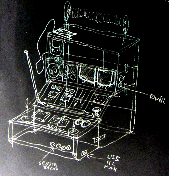
I am going to design and build every module from scratch and include some different and unique modules and parts and try different methods of circuit designing. The frontplates are going to be transparent so all the insides are visible, which adds an extra dimension the the machine - it will be an work of art, from circuit to interface.
I wanted something organic and easy to work with so I went with wooden
frames for the cases and for the front- and backplates I chose
transparent acrylic glass as it's neat to be able to see the insides of
the machine. I will put a lot of emphasis on the aesthetics of the
circuits, parts and components because of this. For attaching the acrylic frontplates I am going to use an alu-rail with rectangular 'slide nuts' as the width of the modules will vary.
In the future I want to be able to
expand with further identical cases on top so I added a mechanism
for attaching the frames to each other. The drawing above shows my vision of what the machine will ultimately end up looking like.
Some snaps of the cases / frames:
Wooden frames with plexi back plate
Single frame / case
Both frames attached
I found it crucial to start with the design of the power supply part. I had an old PSU from a laptop lying around - 19V DC with app. 5A of juice to play around with. Some of the parts will be quite power-hungry so in the future I might have to step it up to 10A. I found a cute old capacitor from Denmark and decided to use it as stabilizing cap. My plan is to have most of the modules run on ±12V but I might add a 5V line as well but so far I've been using LM317 variable voltage regulators for each device.
Power connector and switch w/ LED
Rear view - large capacitor added
Personal notes on PSU
The first actual modules will be a 'terminal' with a green-monochrome CRT TV. It will receive a video signal from an Atmega328 generating simple text strings with data such as the temperature inside the box, total run time, date and time and a lot of other stuff.
Next to it another CRT TV of the same size will display the master stereo output as a simple oscilloscope. Beneath the TV I will install two analog VU meters with a nice warm backlight as well.
Shelf for the TV's and front plate test
Side view of the shelf
Rear view of the CRTs
Both TVs turned on!
VU meters on as well. :-)
Startup-text generated by the arduino
An analog current panel meter will be beneath the terminal showing
the power usage for alle the modules. Each TV draws around 1000 mA but
so far 5A in total should be enough. I've used 7812 regulators for each
TV to supply 12V but the regulators turn very very hot and will shut off
without proper cooling so I had to mount rather large heatsinks.
The
plan is to mount front plates in front of the TV's and have all the
knobs and in/outputs controlling the TV and the terminal.
For labels I want every front plate etched with a CNC router (or just by hand?) and then edge-light it with an LED-strip installed beneath the acrylic. A test looks like this (scrap acrylic with scratches):