I thought I wanted to show you a few shots from where it's all going down - I am located in Aarhus, the 2nd largest city in Denmark, just on the brink of the old Moesgaard forest where I enjoy taking walks and getting in tune with my ancestors.
At home I use our bedroom/office for tinkering and chilling, my lovely woman is very tolerant of the mess I tend to make. My brother dropped by on my 27th birthday with his new fisheye-lense and got some great shots of me in my natural habitat.
To the far right, I've placed my Amiga 600 - a must have memento for the g33ks of the 90's
Caught in the act: at the top shelves are my first tape deck ever, a reel-to-reel tape recorder and an old sine-oscillator
Sending audio signal to small television hacked into an oscilloscope (look in post beneath for how-to)
The sine wave oscillator is a donation from a friend's dad who's a physics teacher. Think it's from the 50's/60's.
This is a demonstration of how you can turn any CRT-television set into a nice visualizer/oscilloscope.
Please take caution when opening up any TV with Cathode Ray Tubes as they can store thousands of volts for a long time after last usage. Use rubber-gloves and ground yourself as a minimum protection. Stay away from the anode (the suction cup hose) as this is the mofo responsible for storing these high voltages.
I take no responsibility for any accidents caused by this guide.
When that's been said - I've fiddled around with quite a few TV-sets during the last couple of years and I have a weakness for very small TV's, so when I came across this Sony Watchman from 1986 (this thing is as old as I am!) which I'd never heard of before, I had to have it as I thought it would be neat as a portable oscilloscope or visualizer for my setup. I am thinking of getting some more of these small CRT's for built-in oscilloscopes in some of my future DIY-synths!
The image to the right shows the Watchman as it were when I bought it, I thought it would be shame to tear it out of its original casing so I decided to keep it intact.
disassembled watchman
gaining access to the PCB
hack done!
In the beginning I wanted just to have it display the horizontal axis for this traditional oscilloscope-mode but the ray is very narrow this way, only taking up a fourth of the area on the screen so I attached a switch for selecting wether to send the signal to both the horizontal and the vertical axis or just the vertical (signal to vertical axis = horizontal line. Check the wiring circuit further down)
This way it functions well both as a visualizer, showing galaxy or whirlwind-like formations or as a small waveform display.
Here's the final result:
For anyone urging to try it out, I made this circuit which should make things a bit more comprehensible. Wire-colouring of the axis' differs for each TV-set but should be easy to locate as they are attached to the end of the tube. And again: DON'T GET ELECTROCUTED!
For quite some time, I've been fascinated about Tape Delays and decided my grand future setup would have to include a DIY Lo-Fi Tape Delay of some sort. I wanted it to be simple, portable and it should colour the sound a great deal, so I chose the Microcassette Tapes for my medium and went off to eBay and bought 2 cheap Dictaphones. Here's the final result, which I am very pleased with
(Thanks to Madst from Dimsos for helping with the nice box!)
The principle of this build is to make a tape loop which goes through both cassettes and past both heads (one for recording, the other for playback) and then feed some of the output from the player back to the recorder for 'repeats'.
I hacked the motor-speed on both boards simply by poking around for bend points on the PCBs - found a point which, when connected to some motor pin, slowed down the speed and one which speeded up the motor speed. But before we could measure the right length of the tape loop, we had to attach the dictaphones on a board with a fixed distance to each other. Next thing is to cut some gaps in the cassettes for the tape loop to run through.
The next thing is the trickiest part and we couldn't do it without 4 hands at least! You need to tape the tape loop on the non-magnetic side and trim the ends for it to fit perfectly. I dread the day I'll have to change the tape 'cause it was a job for magnifying glass and tweezers! But we managed to make it the right size for it not to be too loose or to tight so it would break when the play and record buttons were pushed.
I designed a simple circuit for the signal route. It involves 4 audio potentiometers and 1 linear speed control pot. The audio knobs control 'Input Gain' (the amplitude of the signal being recorded to the tape, 'Feedback/Repeats' (the amplitude of the signal being fed back from the player to the recorder), 'Dry' (the amplitude of the clean signal) and 'Wet' (the amplitude of the output signal from the player).
The signal varies a lot depending on the motor speed, it gets more squeeky at higher speeds, so the feedback amplitude must be lowered a bit. First I got these mad rising amplitudes resulting in undesirable oscillations running haywire so I added a lowpass filter to the circuit which lets through everything under ~7kHz.
It was obvious to box it in a wooden constellation because of the bottom mounting board, so we added some sides and drilled holes for the plexi. I am very pleased with the result, both visually and sonically.
Hi g33kers and Tw33kers, it's been a while. I have a lot of projects going on which I can't wait to show off! But they aren't quite ready yet as I feel best about one larger post for every finalized project.
One thing I have for you though is this newly aquired piece of vintage hardware for a future audio project:
An IBM 8" Floppy Disc Drive from 1971!
This thing is HUGE and the parcel was heavy as F! (shipping cost me more than the drive itself!) Look at the size comparison with that nifty little 3.5" FDD!
I am still in doubt about how to approach this - my goal is clear though: connect the cables from the "tape head" to an audio amp and be able to control the motors (stepper and spindle) as with the other drives.
This is a bit different though.
The spindle motor for spinning the disc is, as far as I am informed, driven off 400V. The stepper motor says 24V, and I've read 5V somewhere around the web. On the PCB, theres a traditional connector for floppy IDE ribbon cables.
The heads have nice accesible wires going the PCB, so it will be extremely easy to extend some wires to the audio amp! That way we can keep this antique piece of computer hardware intact.
Bigger is sometimes better, when it comes to hardware hacking!
Stay tuned!
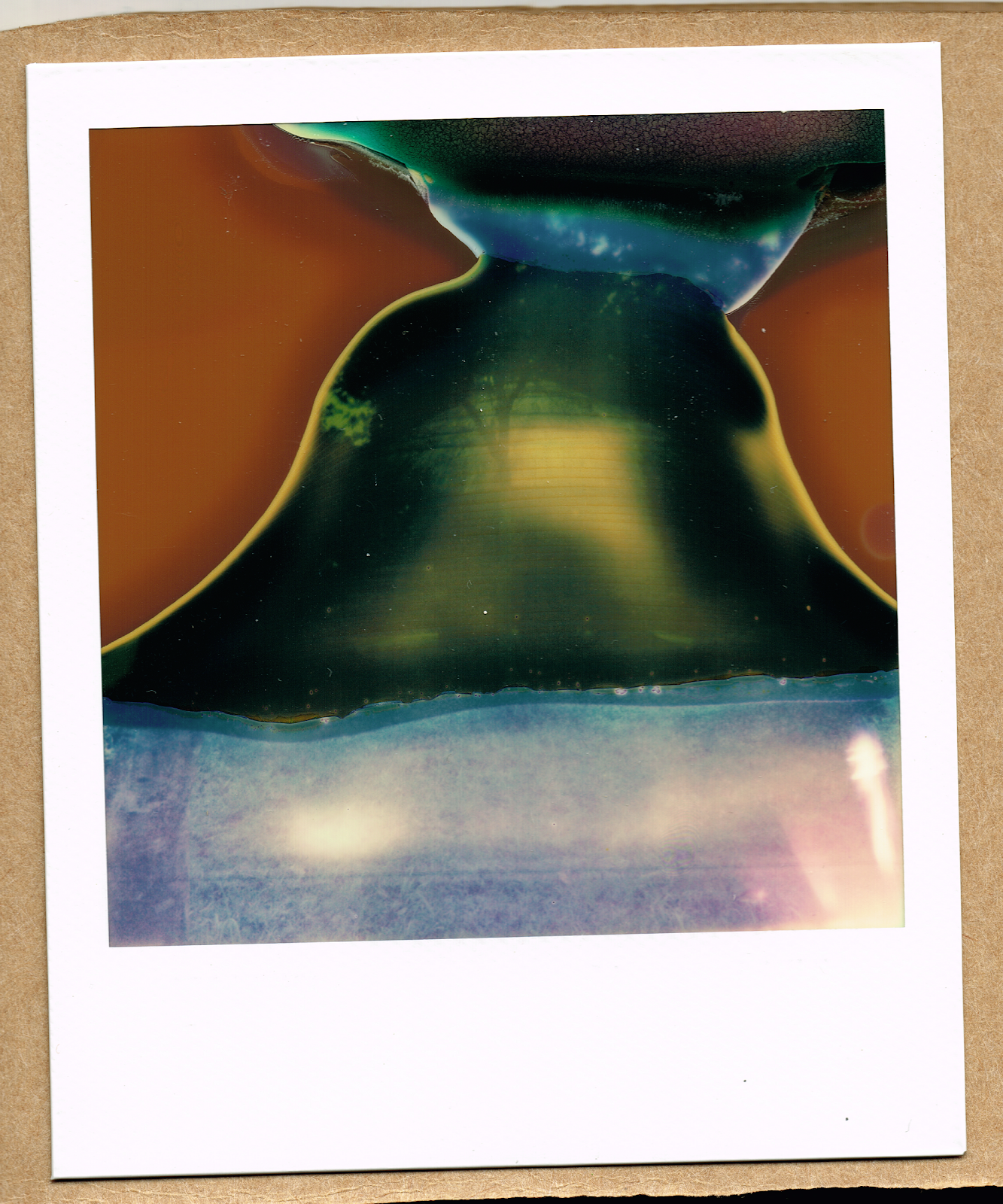
I did some experimentation with a rather new experimental film for Polaroid cameras which I got of The Impossible Project. I got 4 600-films which I wanted to bring to my trek in the Nepalese himalaya mountains last spring for some cool shots.
I guess the last pair of films weren't kept under optimal conditions so some of the critical chemicals involved in the developing of the images leaked or got twisted up in some way which resulted in these bizzare distortions and scrambling of the final images and I decided to name this series The Himalaya Spirit Photos.
I think they could go for some neat cover material or artwork for future releases or just Soundcloud images for various tracks. The weird repeating patterns on the last two images is some sort of chemical leakage which stuck to the rollers that sends out the instant picture and it was printed onto the image.
I bought these super cheap Voice Recordable Audio Greeting Card Modules of eBay for about 1.50$ each. The ones I got has capacity for around 10 seconds of sound. I thought they could be fun having around for a future Lo-Fi sampler, and either ways they were so cheap that there really was no excuse for not buying a bunch.
The module comes with 2 pushbuttons: a record button and a play button. There's a little LED that turns on when record mode is activated and when the message is done playing. There's a small 8 ohm speaker and an electret mic for recording. The module runs of 3 x 1.5V button cell batteries.
Voice Recorder from eBay
Modified into Lo-Fi Looper
The first obvious thing for me was to get rid of these annoying batteries so I connected the bottom connection pad of the first battery holder to GND and the square silver pads in the other corner I connected to 4.5V+. Now we don't have to be concerned about running dry of power.
Next thing was to make this bitch repeat the message when it's done playing. I thought it had to include the pin connected to the PLAY button so I connected a resistor to the pin and sniffed around for a point that would make the message repeat - and as I hoped for, I hit one of the microscopically small SMD-capacitors which (I guess) must go LOW when the message is done playing and then it can function as a signal to repeat the message when connected to PLAY. I did so through af toggle switch, to be able to turn LOOP on/off.
Then I went further in my experimentations and implemented af PITCH pot, just of random experimentation with connecting different points on the PCB: one point slowed down the playback rate; another was speeding it up, so I connected the points to the 'ears' of the potentiometer and Voila! we've got a SPEED knob.
The sound is quite nice and sketchy when pitched almost all the way down! I am having thoughts about turning these into boxed Lo-Fi Loopers and selling them for a fair price. Could be nice to make a small living of circuit bending and handmade electronics :)
More to come in the future about this project! I was just too anxious to be able to keeping this a secret until the final version of the product! And... well, I fried my last PCB by mistake so I am waiting for another shipment from Hong Kong. Hehe.
I was asked by a fellow DIEM-student (Kaj Duncan David), who's arranging avant garde, electro-acoustic and experimental concerts, if I could bring my "Floppy Tape Delay" for a concert.
As you might've read in the post below, I've been preparing my second drive for the gig, with motor speed control and "scrubbing" the stepper motor with a rotary encoder.
So I decided to bring my first drive with the new one and have them run at different speeds in each speaker for weird Steve Reich-ish phase loops and to combine different frequency spectras on the mixer from each drive; i.e. using the lower frequencies from one floppy and the high from the other.
Picture by Jesper Kold
I lacked a decent amplifier for the new drive (it was just running through this Radioshack mini amp and further into the mixer) so it was quite noisy. I kinda liked these very noisy brushes from the gained amp but in the future I will build a small amp circuit for it, as well as the whole arduino controlled stepper motor thing.
My brother brought his camera, once again to get it all on tape. The whole show is there, you might want to jump around for interesting parts if you're not on downers or feel like wasting some time.
So this week on DIEM we had a visit from Gijs Giekses who's an expert in circuit bending, reverse engineering, DIY electronics / syntheseizers and arduino programming. (check his website!)
It was quite introductionary but even though I have some experience with the Arduino it was still nice to be with all the master students at DIEM and Gijs, and to see how they put the microcontroller to use.
Gijs had bought a large box with goodies for the workshop with different types of arduino boards from the tiny Nano boards to some Arduino Megas; there were ultrasonic range-finders, servo motors and all sorts of components for the lots to use.
My good friends from Dimsos were invited to join the workshop as it's very much up their alley. Carl is having arduino-programming as one of his main focuses and I can't wait to show you what we've been up to since august, he and I! It was very nice having them over for the workshop, it was like a giant geeky family!
Gijs introducing the Arduino.
Mads trying out the Nano-board.
The guys from Dimsos visiting.
A couple of days into the workshop and the room was vibrating with code syntax and bleepy noises. Some used the arduino as a composition platform, coding tones and noises from several digital outputs with the ability to make changes in the rythms and patterns with buttons and potentiometers, one guy made and actual synth with the board based on the Auduino library. Some interfaced sensors with Max/MSP and Ableton Live, another guy made a MIDI clock sync box for his hardware. It was just nice seeing the creativity catalysed by the virgin encounter with the arduino. :)
As I had a concert coming up where I was asked to perform with my "Floppy Drive Samplers" I wanted to take the first steps at making the arduino talk to the pins on the FDD. So I had help from Carl The Codemeister and we managed to get a rotary encoder to control the step and direction on the stepper motor. In have future plans about having different patterns and sequences on the atmega-chip to control the stepper motor. (dedicated post to come when the project is finished!)
Bringing my Floppy Disk Drive.
Carl getting data from rotary encoder
Arduino + FDD
On the last day we brought our more intermediate project - an arudino audio player/sampler based on Adafruits WaveShield with 16 step sequencer and display + lots of functions! Still a prototype but soon to be finished! Here's a little shot where we test it with the other workshop contestants (samples on the card are old Amiga soundtracker samples, and 'the amiga' doesn't feel shy to tell you that it's taken over the device :