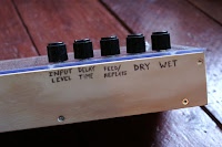
For quite some time, I've been fascinated about Tape Delays and decided my grand future setup would have to include a DIY Lo-Fi Tape Delay of some sort. I wanted it to be simple, portable and it should colour the sound a great deal, so I chose the Microcassette Tapes for my medium and went off to eBay and bought 2 cheap Dictaphones. Here's the final result, which I am very pleased with
(Thanks to Madst from Dimsos for helping with the nice box!)
(Thanks to Madst from Dimsos for helping with the nice box!)
The principle of this build is to make a tape loop which goes through both cassettes and past both heads (one for recording, the other for playback) and then feed some of the output from the player back to the recorder for 'repeats'.
I hacked the motor-speed on both boards simply by poking around for bend points on the PCBs - found a point which, when connected to some motor pin, slowed down the speed and one which speeded up the motor speed. But before we could measure the right length of the tape loop, we had to attach the dictaphones on a board with a fixed distance to each other. Next thing is to cut some gaps in the cassettes for the tape loop to run through.
The next thing is the trickiest part and we couldn't do it without 4 hands at least! You need to tape the tape loop on the non-magnetic side and trim the ends for it to fit perfectly. I dread the day I'll have to change the tape 'cause it was a job for magnifying glass and tweezers! But we managed to make it the right size for it not to be too loose or to tight so it would break when the play and record buttons were pushed.
The signal varies a lot depending on the motor speed, it gets more squeeky at higher speeds, so the feedback amplitude must be lowered a bit. First I got these mad rising amplitudes resulting in undesirable oscillations running haywire so I added a lowpass filter to the circuit which lets through everything under ~7kHz. It was obvious to box it in a wooden constellation because of the bottom mounting board, so we added some sides and drilled holes for the plexi. I am very pleased with the result, both visually and sonically.
I've made a composition with the tape delay and The Microwave Sampler


